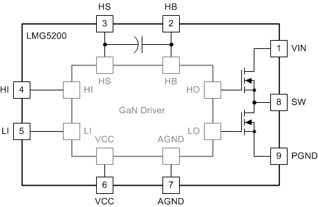
LMG5200 器件集成了 80V、10A 驱动器和 GaN 半桥功率级,采用增强模式氮化镓 (GaN) FET 提供了一套集成功率级解决方案。该器件包含两个 80V GaN FET,它们由采用半桥配置的同一高频 GaN FET 驱动器提供驱动。
GaN FET 在功率转换方面的优势显著,因为其反向恢复电荷几乎为零,输入电容 CISS 也非常小。所有器件均安装在一个完全无键合线的封装平台上,尽可能减少了封装寄生元件数。LMG5200 器件采用 6mm × 8mm × 2mm 无铅封装,可轻松安装在 PCB 上。
该器件的输入与 TTL 逻辑兼容,无论 VCC 电压如何,都能够承受高达 12V 的输入电压。专有的自举电压钳位技术确保了增强模式 GaN FET 的栅极电压处于安全的工作范围内。
该器件配有用户友好型接口且更为出色,进一步提升了分立式 GaN FET 的优势。对于具有高频、高效操作及小尺寸要求的 应用 而言,该器件堪称理想的解决方案。与 TPS53632G 控制器搭配使用时,LMG5200 能够直接将 48V 电压转换为负载点电压 (0.5-1.5V)。
器件型号 | 封装 | 封装尺寸(标称值) |
---|---|---|
LMG5200 | QFM (9) | 6.00mm × 8.00mm |
Changes from C Revision (December 2016) to D Revision
Changes from B Revision (January 2016) to C Revision
Changes from A Revision (March 2015) to B Revision
Changes from * Revision (March 2015) to A Revision
PIN | I/O(1) | DESCRIPTION | |
---|---|---|---|
NAME | NO. | ||
AGND | 7 | G | Analog ground. Ground of driver device. |
HB | 2 | P | High-side gate driver bootstrap rail. |
HI | 4 | I | High-side gate driver control input |
HS | 3 | P | High-side GaN FET source connection |
LI | 5 | I | Low-side driver control input |
PGND | 9 | G | Power ground. Low-side GaN FET source. Electrically shorted to AGND pin. |
SW | 8 | P | Switching node. Electrically shorted to HS pin. Ensure low capacitance at this node on PCB. |
VCC | 6 | P | 5-V positive gate drive supply |
VIN | 1 | P | Input voltage pin. Electrically connected to high-side GaN FET drain. |
PARAMETER | MIN | MAX | UNIT |
---|---|---|---|
VIN to PGND | 0 | 80 | V |
VIN to PGND (pulsed, 100-ms maximum duration)(2) | 100 | V | |
HB to AGND | –0.3 | 86 | V |
HS to AGND | –5 | 80 | V |
HI to AGND | –0.3 | 12 | V |
LI to AGND | –0.3 | 12 | V |
VCC to AGND | –0.3 | 6 | V |
HB to HS | –0.3 | 6 | V |
HB to VCC | 0 | 80 | V |
SW to PGND | –5 | 80 | V |
IOUT from SW pin | 10 | A | |
Junction temperature, TJ | –40 | 125 | °C |
Storage temperature, Tstg | –40 | 150 | °C |
VALUE | UNIT | |||
---|---|---|---|---|
V(ESD) | Electrostatic discharge | Human-body model (HBM), per ANSI/ESDA/JEDEC JS-001(1) | ±1000 | V |
Charged-device model (CDM), per JEDEC specification JESD22-C101(2) |
±500 | V |
MIN | NOM | MAX | UNIT | ||
---|---|---|---|---|---|
VCC | 4.75 | 5 | 5.25 | V | |
LI or HI Input | 0 | 12 | V | ||
VIN | 0 | 80 | V | ||
HS, SW | –5 | 80 | V | ||
HB | VHS + 4 | VHS + 5.25 | V | ||
HS, SW slew rate(1) | 50 | V/ns | |||
Junction temperature, TJ | –40 | 125 | °C |
THERMAL METRIC (1) (2) | LMG5200 | UNIT | |
---|---|---|---|
MOF (QFM) | |||
9 PINS | |||
R θJA | Junction-to-ambient thermal resistance | 35 | °C/W |
R θJC(top) | Junction-to-case (top) thermal resistance | 18 | °C/W |
R θJB | Junction-to-board thermal resistance | 16 | °C/W |
ψ JT | Junction-to-top characterization parameter | 1.8 | °C/W |
ψ JB | Junction-to-board characterization parameter | 16 | °C/W |
PARAMETER | TEST CONDITIONS | MIN | TYP | MAX | UNIT | |
---|---|---|---|---|---|---|
SUPPLY CURRENTS | ||||||
ICC | VCC quiescent current | LI = HI = 0 V, VCC = 5 V, HB-HS = 4.6 V | 0.08 | 0.125 | mA | |
ICCO | Total VCC operating current | f = 500 kHz | 3 | 5 | mA | |
IHB | HB quiescent current | LI = HI = 0 V, VCC = 5 V, HB-HS = 4.6 V | 0.09 | 0.15 | mA | |
IHBO | HB operating current | f = 500 kHz, 50% Duty cycle, VDD = 5 V | 1.5 | 2.5 | mA | |
INPUT PINS | ||||||
VIH | High-level input voltage threshold | Rising edge | 1.87 | 2.06 | 2.22 | V |
VIL | Low-level input voltage threshold | Falling edge | 1.48 | 1.66 | 1.76 | V |
VHYS | Hysteresis between rising and falling threshold | 400 | mV | |||
RI | Input pulldown resistance | 100 | 200 | 300 | kΩ | |
UNDERVOLTAGE PROTECTION | ||||||
VCCR | VCC Rising edge threshold | Rising | 3.2 | 3.8 | 4.5 | V |
VCC(hyst) | VCC UVLO threshold hysteresis | 200 | mV | |||
VHBR | HB Rising edge threshold | Rising | 2.5 | 3.2 | 3.9 | V |
VHB(hyst) | HB UVLO threshold hysteresis | 200 | mV | |||
BOOTSTRAP DIODE | ||||||
VDL | Low-current forward voltage | IVDD-HB = 100 µA | 0.45 | 0.65 | V | |
VDH | High current forward voltage | IVDD-HB = 100 mA | 0.9 | 1.0 | V | |
RD | Dynamic resistance | IVDD-HB = 100 mA | 1.85 | 2.8 | Ω | |
HB-HS clamp | Regulation Voltage | 4.65 | 5 | 5.2 | V | |
tBS | Bootstrap diode reverse recovery time | IF = 100 mA, IR = 100 mA | 40 | ns | ||
QRR | Bootstrap diode reverse recovery charge | VVIN = 50 V | 2 | nC | ||
POWER STAGE | ||||||
RDS(ON)HS | High-side GaN FET on-resistance | LI = 0 V, HI = VCC=5 V, HB-HS = 5 V, VIN-SW = 10 A, TJ = 25℃ | 15 | 20 | mΩ | |
RDS(ON)LS | Low-side GaN FET on-resistance | LI = VCC = 5V, HI = 0 V, HB-HS = 5 V, SW-PGND = 10 A, TJ = 25℃ | 15 | 20 | mΩ | |
VSD | GaN 3rd quadrant conduction drop | ISD = 500 mA, VIN floating, VVCC = 5 V, HI = LI = 0 V | 2 | V | ||
IL-VIN-SW | Leakage from VIN to SW when the high-side GaN FET and low-side GaN FET are off | VIN = 80 V, HI = LI = 0 V, VVCC = 5 V, TJ= 25℃ | 25 | 150 | µA | |
IL-SW-GND | Leakage from SW to GND when the high-side GaN FET and low-side GaN FET are off | SW = 80 V, HI = LI = 0 V, VVCC = 5V, TJ = 25℃ | 25 | 150 | µA | |
COSS | Output capacitance of high-side GaN FET and low-side GaN FET | VDS=40 V, VGS= 0V (HI = LI = 0 V) | 266 | pF | ||
QG | Total gate charge | VDS=40 V, ID= 10A, VGS= 5 V | 3.8 | nC | ||
QOSS | Output charge | VDS=40 V, ID= 10 A | 21 | nC | ||
QRR | Source-to-drain reverse recovery charge | Not including internal driver bootstrap diode | 0 | nC | ||
tHIPLH | Propagation delay: HI rising(2) | LI = 0 V, VCC = 5 V, HB-HS = 5 V, VIN = 30 V | 29.5 | 50 | ns | |
tHIPHL | Propagation delay: HI falling(2) | LI = 0 V, VCC = 5 V, HB-HS = 5 V, VIN = 30 V | 29.5 | 50 | ns | |
tLPLH | Propagation delay: LI rising(2) | HI = 0 V, VCC = 5 V, HB-HS = 5 V, VIN = 30 V | 29.5 | 50 | ns | |
tLPHL | Propagation delay: LI falling(2) | HI = 0 V, VCC = 5 V, HB-HS = 5 V, VIN = 30 V | 29.5 | 50 | ns | |
tMON | Delay matching: LI high and HI low(2) | 2 | 8 | ns | ||
tMOFF | Delay matching: LI low and HI high(2) | 2 | 8 | ns | ||
tPW | Minimum input pulse width that changes the output | 10 | ns |
VDD = 5 V |
VIN = 48 V | VOUT = 5 V | fSW = 1 MHz |
Figure 5 shows the typical test setup used to measure the propagation mismatch. As the gate drives are not accessible, pullup and pulldown resistors in this test circuit are used to indicate when the low-side GaN FET turns ON and the high-side GaN FET turns OFF and vice versa to measure the tMON and tMOFF parameters. Resistance values used in this circuit for the pullup and pulldown resistors are in the order of 1 kΩ; the current sources used are 2 A.
Figure 6 through Figure 9 show propagation delay measurement waveforms. For turnon propagation delay measurements, the current sources are not used. For turnoff time measurements, the current sources are set to 2 A, and a voltage clamp limit is also set, referred to as VIN(CLAMP). When measuring the high-side component turnoff delay, the current source across the high-side FET is turned on, the current source across the low-side FET is off, HI transitions from high-to-low, and output voltage transitions from VIN to VIN(CLAMP). Similarly, for low-side component turnoff propagation delay measurements, the high-side component current source is turned off, and the low-side component current source is turned on, LI transitions from high to low and the output transitions from GND potential to VIN(CLAMP). The time between the transition of LI and the output change is the propagation delay time.