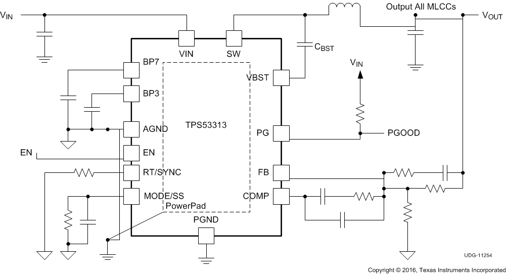
TPS53313 提供集成两个 N 沟道金属氧化物半导体场效应晶体管 (MOSFET) 的 5V 或 12V 同步降压转换器。由于低RDS(接通)和TI私有的 SmoothPWM™跳跃模式操作可优化轻载条件下的效率,同时不影响输出电压纹波。
TPS53313 具有 可编程开关频率(250kHz 至 1.5MHz),可选择跳跃模式或强制 CCM 模式操作。该器件提供预偏置启动、软停止、集成自举开关、电源正常功能和 EN/输入电压锁定 (UVLO) 保护。该器件支持 4.5V 至 16V 范围内的输入电压,无需额外使用偏置电压。可调节输出电压范围:0.6V 至 0.7 × VIN。
TPS53313 采用 4mm × 4mm 24 VQFN 封装(绿色环保,符合 RoHS 标准并且无铅),额定运行温度范围为 -40°C 至 85°C。
器件型号 | 封装 | 封装尺寸(标称值) |
---|---|---|
TPS53313 | VQFN (24) | 4.00mm x 4.00mm |
PIN | TYPE(1) | DESCRIPTION | |
---|---|---|---|
NO. | NAME | ||
1 | EN | I | Enable pin |
2 | PG | O | Power good output flag. Open drain output. Pull up to an external rail through a resistor. |
3 | VIN | P | Gate driver supply and power conversion voltage |
4 | VIN | P | Gate driver supply and power conversion voltage |
5 | VIN | P | Gate driver supply and power conversion voltage |
6 | VIN | P | Gate driver supply and power conversion voltage |
7 | PGND | P | Device power ground terminal |
8 | PGND | P | Device power ground terminal |
9 | PGND | P | Device power ground terminal |
10 | PGND | P | Device power ground terminal |
11 | PGND | P | Device power ground terminal |
12 | PGND | P | Device power ground terminal |
13 | SW | O | Output inductor connection to integrated power devices |
14 | SW | O | Output inductor connection to integrated power devices |
15 | SW | O | Output inductor connection to integrated power devices |
16 | SW | O | Output inductor connection to integrated power devices |
17 | VBST | P | Supply input for high-side MOSFET (bootstrap terminal). Connect capacitor from this pin to SW terminal. |
18 | BP7 | P | Bias for internal circuitry and driver |
19 | BP3 | P | Input bias supply for analog functions |
20 | AGND | G | Device analog ground terminal |
21 | RT/SYNC | I/O | Synchronized to external clock. Program the switching frequency by connecting with a resistor to GND. |
22 | MODE/SS | I | Mode configuration pin. Connect with a resistor to GND sets different modes and soft-start time, parallel a capacitor (or no capacitor) with the resistor changes the current limit threshold. Shorting MODE/SS pin to supply inhibits the device; shorting MODE/SS pin to AGND is equivalent to 10-kΩ resistor setting is not recommended (see Table 1 and Table 2 for resistor and capacitor settings). |
23 | COMP | O | Error amplifier compensation terminal. Type III compensation method is generally recommended for stability. |
24 | FB | I | Voltage feedback pin. Use for OVP, UVP, and power good determination |
MIN | MAX | UNIT | |||
---|---|---|---|---|---|
Input voltage | VIN | –0.3 | 20 | V | |
VBST | –0.3 | 27 | |||
VBST to SW | –0.3 | 7 | |||
SW (bidirectional) | DC | –2 | 20 | ||
transient < 20 ns | –3 | 20 | |||
EN | VVIN ≥ 17 | –0.3 | 17 | ||
VVIN < 17 | –0.3 | VVIN + 0.1 | |||
FB, MODE/SS | –0.3 | 3.6 | |||
Output voltage | COMP, RT/SYNC, BP3 | –0.3 | 3.6 | V | |
BP7 | –0.3 | 7 | |||
PGD | –0.3 | 17 | |||
Ground pin (GND) | –0.3 | 0.3 | V | ||
Output current | 6 | A | |||
Operating temperature, TJ | –40 | 150 | °C | ||
Storage temperature, Tstg | –55 | 150 | °C |
VALUE | UNIT | |||
---|---|---|---|---|
V(ESD) | Electrostatic discharge | Human-body model (HBM), per ANSI/ESDA/JEDEC JS-001(1) | ±2000 | V |
Charged-device model (CDM), per JEDEC specification JESD22-C101(2) | ±500 |
MIN | MAX | UNIT | ||||
---|---|---|---|---|---|---|
Input voltage | VIN (main supply) | 4.5 | 16 | V | ||
VBST | –0.1 | 22 | ||||
VBST to SW | –0.1 | 6.5 | ||||
SW (bidirectional) | dc | –1 | 18 | |||
transient < 20 ns | –2 | 18 | ||||
EN | –0.1 | VVIN + 0.1 | ||||
FB, MODE/SS | –0.1 | 3.5 | ||||
Output voltage | COMP, RT/SYNC, BP3 | –0.1 | 3.5 | V | ||
BP7 | –0.1 | 6.5 | ||||
PGD | –0.1 | 14 | ||||
Ground pin (GND) | –0.1 | 0.1 | V | |||
TA | Ambient temperature | –40 | 85 | °C | ||
TJ | Junction temperature | –40 | 125 | °C |
THERMAL METRIC(1) | TPS53313 | UNIT | |
---|---|---|---|
RGE (VQFN) | |||
24 PINS | |||
RθJA | Junction-to-ambient thermal resistance | 44.1 | °C/W |
RθJC(top) | Junction-to-case (top) thermal resistance | 35 | °C/W |
RθJB | Junction-to-board thermal resistance | 19 | °C/W |
ψJT | Junction-to-top characterization parameter | 0.5 | °C/W |
ψJB | Junction-to-board characterization parameter | 18.8 | °C/W |
RθJC(bot) | Junction-to-case (bottom) thermal resistance | 8.9 | °C/W |
PARAMETER | TEST CONDITIONS | MIN | TYP | MAX | UNIT | |
---|---|---|---|---|---|---|
INPUT SUPPLY | ||||||
VVIN | VIN supply voltage | Nominal input voltage range | 4.5 | 16 | V | |
VPOR | VIN POR threshold | Ramp up, EN = HIGH | 4 | 4.23 | 4.4 | V |
VPOR(hys) | VIN POR hysteresis | 200 | mV | |||
ISTBY | Standby current | EN = LOW, VIN = 12 V | 58 | µA | ||
RBOOT | Bootstrap on-resistance | 10 | Ω | |||
REFERENCE | ||||||
VVREF | Internal precision reference voltage | 0.6 | V | |||
TOLVREF | VREF tolerance | –1% | 1% | |||
ERROR AMPLIFIER | ||||||
UGBW(1) | Unity gain bandwidth | 14 | MHz | |||
AOL(1) | Open loop gain | 80 | dB | |||
IFBINT | FB input leakage current | Sourced from FB pin | 50 | nA | ||
IEA(max) | Output sinking and sourcing current | 5 | mA | |||
SR(1) | Slew rate | 5 | V/µs | |||
ENABLE | ||||||
RENPD(1) | Enable pulldown resistor | 800 | kΩ | |||
VENH | EN logic high | VVIN = 4.5 V | 1.8 | V | ||
VENHYS | EN hysteresis | VVIN = 4.5 V | 0.6 | V | ||
IEN | EN pin current | VEN = 0 V | 1 | µA | ||
VEN = 3.3 V | 3.3 | 5 | ||||
VEN = 14 V | 17.8 | 27.5 | ||||
SOFT-START | ||||||
tSS_1 | Delay after EN asserts | EN = High | 0.65 | ms | ||
tSS_2 | Soft start ramp_up time | 0 V ≤ VSS ≤ 0.6 V, 39-kΩ or no resistor to MODE/SS pin | 1 | ms | ||
0 V ≤ VSS ≤ 0.6 V, 20-kΩ or 160-kΩ resistor to MODE/SS pin | 3 | |||||
0 V ≤ VSS ≤ 0.6 V, 10-kΩ or 82-kΩ resistor to MODE/SS pin | 6 | |||||
tPGDENDLY | PGD startup delay time | VSS = 0.6 V to PGD (SSOK) going high, tSS = 1 ms |
0.2 | ms | ||
RAMP | ||||||
Ramp amplitude | 4.5 V ≤ VVIN ≤ 14.4 V | VVIN/9 | V | |||
14.4 V ≤ VVIN ≤ 16 V | 1.6 | |||||
PWM | ||||||
tMIN(off) | Minimum OFF time | fSW = 1 MHz | 150 | ns | ||
tMIN(on) | Minimum ON time | No load | 90 | ns | ||
DMAX | Maximum duty cycle | fSW = 1 MHz | 80% | |||
SWITCHING FREQUENCY | ||||||
fSW | Switching frequency tolerance | fSW = 1 MHz, RT = 45.3 kΩ | –10% | 10% | ||
SOFT DISCHARGE | ||||||
RSFTDIS | Soft-discharge transistor resistance | EN = Low, VIN = 4.5 V, VOUT = 0.6 V | 120 | Ω | ||
OVERCURRENT AND ZERO CROSSING | ||||||
IOCPL | Overcurrent limit on high-side FET (peak) | When IOUT exceeds this threshold for 4 consecutive cycles, 2.2-nF capacitor to MODE/SS pin | 4.5 | A | ||
When IOUT exceeds this threshold for 4 consecutive cycles, no capacitor to MODE/SS pin | 6 | A | ||||
When IOUT exceeds this threshold for 4 consecutive cycles, 10-nF capacitor to MODE/SS pin | 9 | |||||
IOCPH | One time overcurrent shut-off on the low-side FET (peak) | Immediately shut down when sensed current reach this value, 2.2-nF capacitor to MODE/SS pin | 4.5 | A | ||
Immediately shut down when sensed current reach this value, no capacitor to MODE/SS pin | 6 | A | ||||
Immediately shut down when sensed current reach this value, 10-nF capacitor to MODE/SS pin | 9 | |||||
VZXOFF | Zero crossing comparator internal offset | SW – PGND, SKIP mode | –3 | mV | ||
POWER GOOD | ||||||
VPGDL | Power good low threshold | Measured at the FB pin w/r/t VREF | 80% | 83% | 86% | |
VPGDH | Power good high threshold | Measured at the FB pin w/r/t VREF | 114% | 117% | 120% | |
VPG(hys) | Power good hysteresis | 2 | ||||
VIN(min_pg) | Minimum Vin voltage for valid PG at startup. | Measured at VIN with 1-mA (or 2-mA) sink current on PG pin at startup | 1 | V | ||
VPG(pd) | Power good pull-down voltage | Pull down voltage with 4-mA sink current | 0.2 | 0.4 | V | |
IPG(leak) | Power good leakage current | Hi-Z leakage current, apply 3.3-V in off state | 12 | 16.2 | µA | |
OUTPUT OVERVOLTAGE AND UNDERVOLTAGE PROTECTION | ||||||
TOVPDLY | Overvoltage protection delay time | Time from FB out of +17% of VREF to OVP fault | 2 | µs | ||
TUVPDLY | Undervoltage protection delay time | Time from FB out of –17% of VREF to UVP fault | 10 | µs | ||
THERMAL SHUTDOWN | ||||||
THSD(1) | Thermal shutdown | Shutdown controller, attempt soft-stop | 130 | 140 | 150 | °C |
THSDHYST(1) | Thermal shutdown hysteresis | Controller restarts after temperature drops | 40 | °C |