ISO5451-Q1 是一款用于 IGBT 和 MOSFET 的 5.7 kVRMS 增强型隔离栅极驱动器,具有 2.5A 的拉电流能力和 5A 的灌电流能力。输入端由 3V 至 5.5V 的单电源供电运行。输出端允许的电源范围为 15V 至 30V。两个互补 CMOS 输入控制栅极驱动器的输出状态。76ns 的短暂传播时间保证了对于输出级的精确控制。
内置的去饱和 (DESAT) 故障检测功能可识别 IGBT 何时处于过载状态。当检测到 DESAT 时,栅极驱动器输出会被拉低为 VEE2 电势,从而将 IGBT 立即关断。
器件型号 | 封装 | 封装尺寸(标称值) |
---|---|---|
ISO5451-Q1 | SOIC (16) | 10.30mm x 7.50mm |
日期 | 修订版本 | 注释 |
---|---|---|
2016 年 9 月 | * | 最初发布版本 |
当发生去饱和故障时,器件会通过隔离隔栅发送故障信号,以将输入端的 FLT 输出拉为低电平并阻断隔离器的输入。FLT 的输出状态将被锁存,可通过 RST 输入上的低电平有效脉冲复位。
如果在由双极输出电源供电的正常运行期间关断 IGBT,输出电压会被硬钳位为 VEE2。如果输出电源为单极,那么可采用有源米勒钳位,这种钳位会在一条低阻抗路径上灌入米勒电流,从而防止 IGBT 在高电压瞬态条件下发生动态导通。
栅极驱动器是否准备就绪待运行由两个欠压锁定电路控制,这两个电路会监视输入端和输出端的电源。如果任意一端电源不足,RDY 输出会变为低电平,否则该输出为高电平。
ISO5451-Q1 采用 16 引脚小外形尺寸集成电路 (SOIC) 封装。此器件的额定工作环境温度范围为 -40°C 至 125°C。
PIN | I/O | DESCRIPTION | |
---|---|---|---|
NAME | NO. | ||
VEE2 | 1, 8 | - | Output negative supply. Connect to GND2 for Unipolar supply application. |
DESAT | 2 | I | Desaturation voltage input |
GND2 | 3 | - | Gate drive common. Connect to IGBT emitter. |
NC | 4 | - | Not connected |
VCC2 | 5 | - | Most positive output supply potential. |
OUT | 6 | O | Gate drive voltage output |
CLAMP | 7 | O | Miller clamp output |
GND1 | 9, 16 | - | Input ground |
IN+ | 10 | I | Non-inverting gate drive voltage control input |
IN- | 11 | I | Inverting gate drive voltage control input |
RDY | 12 | O | Power-good output, active high when both supplies are good. |
FLT | 13 | O | Fault output, low-active during DESAT condition |
RST | 14 | I | Reset input, apply a low pulse to reset fault latch. |
VCC1 | 15 | - | Positive input supply (3 V to 5.5 V) |
MIN | MAX | UNIT | ||||
---|---|---|---|---|---|---|
VCC1 | Supply voltage input side | GND1 - 0.3 | 6 | V | ||
VCC2 | Positive supply voltage output side | (VCC2 – GND2) | –0.3 | 35 | V | |
VEE2 | Negative supply voltage output side | (VEE2 – GND2) | –17.5 | 0.3 | V | |
V(SUP2) | Total supply output voltage | (VCC2 - VEE2) | –0.3 | 35 | V | |
VOUT | Gate driver output voltage | VEE2 - 0.3 | VCC2 + 0.3 | V | ||
I(OUTH) | Gate driver high output current | Gate driver high output current (max pulse width = 10 μs, max duty cycle = 0.2%) |
2.7 | A | ||
I(OUTL) | Gate driver low output current | 5.5 | A | |||
V(LIP) | Voltage at IN+, IN-, FLT, RDY, RST | GND1 - 0.3 | VCC1 + 0.3 | V | ||
I(LOP) | Output current of FLT, RDY | 10 | mA | |||
V(DESAT) | Voltage at DESAT | GND2 - 0.3 | VCC2 + 0.3 | V | ||
V(CLAMP) | Clamp voltage | VEE2 - 0.3 | VCC2 + 0.3 | V | ||
TJ | Junction temperature | –40 | 150 | °C | ||
TSTG | Storage temperature | -65 | 150 | °C |
VALUE | UNIT | |||
---|---|---|---|---|
V(ESD) | Electrostatic discharge | Human-body model (HBM), per AEC Q100-002(1) | ±4000 | V |
Charged-device model (CDM), per AEC Q100-011 | ±1500 |
MIN | NOM | MAX | UNIT | ||
---|---|---|---|---|---|
VCC1 | Supply voltage input side | 3 | 5.5 | V | |
VCC2 | Positive supply voltage output side (VCC2 – GND2) | 15 | 30 | V | |
VEE2 | Negative supply voltage output side (VEE2 – GND2) | –15 | 0 | V | |
V(SUP2) | Total supply voltage output side (VCC2 – VEE2) | 15 | 30 | V | |
VIH | High-level input voltage (IN+, IN-, RST) | 0.7 x VCC1 | VCC1 | V | |
VIL | Low-level input voltage (IN+, IN-, RST) | 0 | 0.3 x VCC1 | V | |
tUI | Pulse width at IN+, IN- for full output (CLOAD = 1nF) | 40 | ns | ||
tRST | Pulse width at RST for resetting fault latch | 800 | ns | ||
TA | Ambient temperature | -40 | 25 | 125 | °C |
THERMAL METRIC(1) | DW (SOIC) | UNIT | |
---|---|---|---|
16 PINS | |||
RθJA | Junction-to-ambient thermal resistance | 99.6 | °C/W |
RθJC(top) | Junction-to-case (top) thermal resistance | 48.5 | |
RθJB | Junction-to-board thermal resistance | 56.5 | |
ψJT | Junction-to-top characterization parameter | 29.2 | |
ψJB | Junction-to-board characterization parameter | 56.5 |
VALUE | UNIT | |||
---|---|---|---|---|
PD | Maximum power dissipation(1) | 1255 | mW | |
PID | Maximum input power dissipation | 175 | ||
POD | Maximum output power dissipation | 1080 |
PARAMETER | TEST CONDITIONS | SPECIFICATION | UNIT | |
---|---|---|---|---|
CLR | External clearance(1) | Shortest terminal-to-terminal distance through air | >8 | mm |
CPG | External creepage(1) | Shortest terminal-to-terminal distance across the package surface | >8 | mm |
DTI | Distance through the insulation | Minimum internal gap (internal clearance) | >21 | μm |
CTI | Tracking resistance (comparative tracking index) | DIN EN 60112 (VDE 0303-11); IEC 60112; | >600 | V |
Material Group | According to IEC 60664-1; UL 746A | I | ||
Overvoltage category (according to IEC 60664-1) | Rated Mains Voltage ≤ 300 VRMS | I-IV | ||
Rated Mains Voltage ≤ 600 VRMS | I-III | |||
Rated Mains Voltage ≤ 1000 VRMS | I-II | |||
DIN V VDE V 0884-10 (VDE V 0884-10):2006-12(2) | ||||
VIORM | Maximum repetitive peak isolation voltage | AC voltage (bipolar) | 1420 | VPK |
VIOWM | Maximum isolation working voltage | AC voltage. Time dependent dielectric breakdown (TDDB) Test, see Figure 1 | 1000 | VRMS |
DC voltage | 1420 | VDC | ||
VIOTM | Maximum Transient isolation voltage | VTEST = VIOTM, t = 60 sec (qualification), t = 1 sec (100% production) | 8000 | VPK |
VIOSM | Maximum surge isolation voltage(3) | Test method per IEC 60065, 1.2/50 μs waveform, VTEST = 1.6 x VIOSM = 10000 VPK (qualification)(3) |
6250 | |
qpd | Apparent charge(4) | Method a: After I/O safety test subgroup 2/3, Vini = VIOTM, tini = 60 s; Vpd(m) = 1.2 × VIORM = 1704 VPK , tm = 10 s |
≤5 | pC |
Method a: After environmental tests subgroup 1, Vini = VIOTM, tini = 60 s; Vpd(m) = 1.6 × VIORM = 2272 VPK , tm = 10 s |
≤5 | |||
Method b1: At routine test (100% production) and preconditioning (type test) Vini = VIOTM, tini = 60 s; Vpd(m) = 1.875× VIORM = 2663 VPK , tm = 10 s |
≤5 | |||
RIO | Isolation resistance, input to output(5) | VIO = 500 V, TA = 25°C | > 1012 | Ω |
VIO = 500 V, 100°C ≤ TA ≤ 125°C | > 1011 | Ω | ||
VIO = 500 V at TS = 150°C | > 109 | Ω | ||
CIO | Barrier capacitance, input to output(5) | VIO = 0.4 x sin (2πft), f = 1 MHz | 1 | pF |
Pollution degree | 2 | |||
UL 1577 | ||||
VISO | Withstanding Isolation voltage | VTEST = VISO, t = 60 sec (qualification), VTEST = 1.2 × VISO = 6840 VRMS, t = 1 sec (100% production) |
5700 | VRMS |
PARAMETER | TEST CONDITIONS | MIN | TYP | MAX | UNIT | ||
---|---|---|---|---|---|---|---|
IS | Safety input, output or supply current | θJA = 99.6°C/W, VI = 3.6 V, TJ = 150°C, TA = 25°C |
349 | mA | |||
θJA = 99.6°C/W, VI = 5.5 V, TJ = 150°C, TA = 25°C |
228 | ||||||
θJA = 99.6°C/W, VI = 15 V, TJ = 150°C, TA = 25°C |
84 | ||||||
θJA = 99.6°C/W, VI = 30 V, TJ = 150°C, TA = 25°C |
42 | ||||||
PS | Safety input, output, or total power | θJA = 99.6°C/W, TJ = 150°C, TA = 25°C | 1255(1) | ||||
TS | Maximum ambient safety temperature | 150 | °C |
VDE | CSA | UL | CQC | TUV |
---|---|---|---|---|
Certified according to DIN V VDE V 0884-10 (VDE V 0884-10):2006-12 and DIN EN 60950-1 (VDE 0805 Teil 1):2011-01 |
Plan to certify under CSA Component Acceptance Notice 5A, IEC 60950-1 and IEC 60601-1 | Certified according to UL 1577 Component Recognition Program | Certified according to GB 4943.1-2011 | Certified according to EN 61010-1:2010 (3rd Ed) and EN 60950-1:2006/A11:2009/A1:2010/ A12:2011/A2:2013 |
Reinforced Insulation Maximum Transient isolation voltage, 8000 VPK; Maximum surge isolation voltage, 6250 VPK, Maximum repetitive peak isolation voltage, 1420 VPK |
Isolation Rating of 5700 VRMS; Reinforced insulation per CSA 60950- 1- 07+A1+A2 and IEC 60950-1 (2nd Ed.), 800 VRMS max working voltage (pollution degree 2, material group I) ; 2 MOPP (Means of Patient Protection) per CSA 60601-1:14 and IEC 60601-1 Ed. 3.1, 250 VRMS (354 VPK) max working voltage |
Single Protection, 5700 VRMS (1) | Reinforced Insulation, Altitude ≤ 5000m, Tropical climate, 400 VRMS maximum working voltage | 5700 VRMS Reinforced insulation per EN 61010-1:2010 (3rd Ed) up to working voltage of 600 VRMS 5700 VRMS Reinforced insulation per EN 60950-1:2006/A11:2009/A1:2010/ A12:2011/A2:2013 up to working voltage of 800 VRMS |
Certification completed Certificate number: 40040142 |
Certification planned | Certification completed File number: E181974 |
Certification completed Certificate number: CQC16001141761 |
Certification completed Client ID number: 77311 |
The safety-limiting constraint is the absolute-maximum junction temperature specified in the Absolute Maximum Ratings table. The power dissipation and junction-to-air thermal impedance of the device installed in the application hardware determines the junction temperature. The assumed junction-to-air thermal resistance in the Thermal Information table is that of a device installed in the High-K Test Board for Leaded Surface-Mount Packages. The power is the recommended maximum input voltage times the current. The junction temperature is then the ambient temperature plus the power times the junction-to-air thermal resistance.
PARAMETER | TEST CONDITIONS | MIN | TYP | MAX | UNIT | ||
---|---|---|---|---|---|---|---|
VOLTAGE SUPPLY | |||||||
VIT+(UVLO1) | Positive-going UVLO1 threshold voltage input side (VCC1 – GND1) | 2.25 | V | ||||
VIT-(UVLO1) | Negative-going UVLO1 threshold voltage input side (VCC1 – GND1) | 1.7 | V | ||||
VHYS(UVLO1) | UVLO1 Hysteresis voltage (VIT+ – VIT–) input side | 0.24 | V | ||||
VIT+(UVLO2) | Positive-going UVLO2 threshold voltage output side (VCC2 – GND2) | 12 | 13 | V | |||
VIT-(UVLO2) | Negative-going UVLO2 threshold voltage output side (VCC2 – GND2) | 9.5 | 11 | V | |||
VHYS(UVLO2) | UVLO2 Hysteresis voltage (VIT+ – VIT–) output side | 1 | V | ||||
IQ1 | Input supply quiescent current | 2.8 | 4.5 | mA | |||
IQ2 | Output supply quiescent current | 3.6 | 6 | mA | |||
LOGIC I/O | |||||||
VIT+(IN,RST) | Positive-going input threshold voltage (IN+, IN-, RST) | 0.7 x VCC1 | V | ||||
VIT-(IN,RST) | Negative-going input threshold voltage (IN+, IN-, RST) | 0.3 x VCC1 | V | ||||
VHYS(IN,RST) | Input hysteresis voltage (IN+, IN-, RST) | 0.15 x VCC1 | V | ||||
IIH | High-level input leakage at (IN+) (1) | IN+ = VCC1 | 100 | µA | |||
IIL | Low-level input leakage at (IN-, RST) (2) | IN- = GND1, RST = GND1 | -100 | µA | |||
IPU | Pull-up current of FLT, RDY | V(RDY) = GND1, V(FLT) = GND1 | 100 | µA | |||
VOL | Low-level output voltage at FLT, RDY | I(FLT) = 5 mA | 0.2 | V | |||
GATE DRIVER STAGE | |||||||
V(OUTPD) | Active output pull-down voltage | IOUT = 200 mA, VCC2 = open | 2 | V | |||
V(OUTH) | High-level output voltage | IOUT = –20 mA | VCC2 - 0.5 | VCC2 - 0.24 | V | ||
V(OUTL) | Low-level output voltage | IOUT = 20 mA | VEE2 + 13 | VEE2 + 50 | mV | ||
I(OUTH) | High-level output peak current | IN+ = high, IN- = low, VOUT = VCC2 - 15 V |
1.5 | 2.5 | A | ||
I(OUTL) | Low-level output peak current | IN+ = low, IN- = high, VOUT = VEE2 + 15 V |
3.4 | 5 | A | ||
ACTIVE MILLER CLAMP | |||||||
V(CLP) | Low-level clamp voltage | I(CLP) = 20 mA | VEE2 + 0.015 | VEE2 + 0.08 | V | ||
I(CLP) | Low-level clamp current | V(CLAMP) = VEE2 + 2.5 V | 1.6 | 2.5 | A | ||
V(CLTH) | Clamp threshold voltage | 1.6 | 2.1 | 2.5 | V | ||
SHORT CIRCUIT CLAMPING | |||||||
V(CLP_OUT) | Clamping voltage (VOUT - VCC2) |
IN+ = high, IN- = low, tCLP=10 µs, I(OUTH) = 500 mA | 0.8 | 1.3 | V | ||
V(CLP_CLAMP) | Clamping voltage (VCLP - VCC2) |
IN+ = high, IN- = low, tCLP=10 µs, I(CLP) = 500 mA | 1.3 | V | |||
V(CLP_CLAMP) | Clamping voltage at CLAMP | IN+ = High, IN- = Low, I(CLP) = 20 mA | 0.7 | 1.1 | V | ||
DESAT PROTECTION | |||||||
I(CHG) | Blanking capacitor charge current | V(DESAT) - GND2 = 2 V | 0.42 | 0.5 | 0.58 | mA | |
I(DCHG) | Blanking capacitor discharge current | V(DESAT) - GND2 = 6 V | 9 | 14 | mA | ||
V(DSTH) | DESAT threshold voltage with respect to GND2 | 8.3 | 9 | 9.5 | V | ||
V(DSL) | DESAT voltage with respect to GND2, when OUT is driven low | 0.4 | 1 | V |
PARAMETER | TEST CONDITIONS | MIN | TYP | MAX | UNIT | |
---|---|---|---|---|---|---|
tr | Output signal rise time | CLOAD = 1 nF, see Figure 38, Figure 39 and Figure 40 | 12 | 20 | 35 | ns |
tf | Output signal fall time | 12 | 20 | 37 | ns | |
tPLH, tPHL | Propagation Delay | 76 | 110 | ns | ||
tsk-p | Pulse Skew |tPHL – tPLH| | 20 | ns | |||
tsk-pp | Part-to-part skew | 30(1) | ns | |||
tGF | Glitch filter on IN+, IN-, RST | 20 | 30 | 40 | ns | |
tDESAT (10%) | DESAT sense to 10% OUT delay | 300 | 415 | 500 | ns | |
tDESAT (GF) | DESAT glitch filter delay | 330 | ns | |||
tDESAT (FLT) | DESAT sense to FLT-low delay | see Figure 40 | 2000 | 2420 | ns | |
tLEB | Leading edge blanking time | see Figure 38 and Figure 39 | 330 | 400 | 500 | ns |
tGF(RSTFLT) | Glitch filter on RST for resetting FLT | 300 | 800 | ns | ||
CI | Input capacitance(2) | VI = VCC1/2 + 0.4 x sin (2πft), f = 1 MHz, VCC1 = 5 V |
2 | pF | ||
CMTI | Common-mode transient immunity | VCM = 1500 V, see Figure 41 | 50 | 100 | kV/μs |
TA upto 150°C | Stress-voltage frequency = 60 Hz |
VCC2 = 30 V |
Unipolar: VCC2 - VEE2 = VCC2 - GND2 |
VCC2 = 30 V |
CL = 1 nF | RG = 0 Ω | |
VCC2 - VEE2 = VCC2 - GND2 = 20 V |
CL = 10 nF | RG = 0 Ω | |
VCC2 - VEE2 = VCC2 - GND2 = 20 V |
CL = 100 nF | RG = 0 Ω | |
VCC2 - VEE2 = VCC2 - GND2 = 20 V |
CL = 100 nF | RG = 10 Ω | |
VCC2 - VEE2 = VCC2 - GND2 = 20 V |
IN+ = Low | IN- = Low |
RG = 10 Ω, 20kHz |
CL = 1nF | RG = 0 Ω | VCC2 = 15 V |
RG = 0 Ω | VCC1 = 5 V |
RG = 10 Ω | VCC1 = 5 V |
CL = 1 nF |
VCC2 = 15 V | DESAT = 6 V |
CL = 1 nF | RG = 10 Ω | |
VCC2 - VEE2 = VCC2 - GND2 = 20 V |
CL = 10 nF | RG = 10 Ω | |
VCC2 - VEE2 = VCC2 - GND2 = 20 V |
CL = 100 nF | RG = 10 Ω | |
VCC2 - VEE2 = VCC2 - GND2 = 20 V |
IN+ = High | IN- = Low |
Input Frequency = 1 kHz |
No CL |
CL = 1nF | RG = 0 Ω | VCC1 = 5 V |
RG = 10 Ω | VCC1 = 5 V |
RG = 0 Ω | VCC1 = 5 V |
RG = 10 Ω | VCC1 = 5 V |
CL = 10 nF |
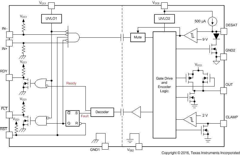
The ISO5451-Q1 is an isolated gate driver for IGBTs and MOSFETs. Input CMOS logic and output power stage are separated by a capacitive, silicon dioxide (SiO2), isolation barrier.
The IO circuitry on the input side interfaces with a micro controller and consists of gate drive control and RESET (RST) inputs, READY (RDY) and FAULT (FLT) alarm outputs. The power stage consists of power transistors to supply 2.5-A pull-up and 5-A pull-down currents to drive the capacitive load of the external power transistors, as well as DESAT detection circuitry to monitor IGBT collector-emitter overvoltage under short circuit events. The capacitive isolation core consists of transmit circuitry to couple signals across the capacitive isolation barrier, and receive circuitry to convert the resulting low-swing signals into CMOS levels. The ISO5451-Q1 also contains under voltage lockout circuitry to prevent insufficient gate drive to the external IGBT, and active output pull-down feature which ensures that the gate-driver output is held low, if the output supply voltage is absent. The ISO5451-Q1 also has an active Miller clamp function which can be used to prevent parasitic turn-on of the external power transistor, due to Miller effect, for unipolar supply operation.
The ISO5451-Q1 supports both bipolar and unipolar power supply with active Miller clamp.
For operation with bipolar supplies, the IGBT is turned off with a negative voltage on its gate with respect to its emitter. This prevents the IGBT from unintentionally turning on because of current induced from its collector to its gate due to Miller effect. In this condition it is not necessary to connect CLAMP output of the gate driver to the IGBT gate, but connecting CLAMP output of the gate driver to the IGBT gate is also not an issue. Typical values of VCC2 and VEE2 for bipolar operation are 15 V and -8 V with respect to GND2.
For operation with unipolar supply, typically, VCC2 is connected to 15 V with respect to GND2, and VEE2 is connected to GND2. In this use case, the IGBT can turn-on due to additional charge from IGBT Miller capacitance caused by a high voltage slew rate transition on the IGBT collector. To prevent IGBT to turn on, the CLAMP pin is connected to IGBT gate and Miller current is sinked through a low impedance CLAMP transistor.
Miller CLAMP is designed for miller current up to 2 A. When the IGBT is turned-off and the gate voltage transitions below 2 V the CLAMP current output is activated.
The Active output pull-down feature ensures that the IGBT gate OUT is clamped to VEE2 to ensure safe IGBT off-state when the output side is not connected to the power supply.
Undervoltage Lockout (UVLO) ensures correct switching of IGBT. The IGBT is turned-off, if the supply VCC1 drops below VIT-(UVLO1), irrespective of IN+, IN- and RST input till VCC1 goes above VIT+(UVLO1).
In similar manner, the IGBT is turned-off, if the supply VCC2 drops below VIT-(UVLO2), irrespective of IN+, IN- and RST input till VCC2 goes above VIT+(UVLO2).
Ready (RDY) pin indicates status of input and output side Under Voltage Lock-Out (UVLO) internal protection feature. If either side of device have insufficient supply (VCC1 or VCC2), the RDY pin output goes low; otherwise, RDY pin also serves as an indication to the micro-controller that the device is ready for operation.
During IGBT overload condition, to report desaturation error FLT goes low. If RST is held low for the specified duration, FLT is cleared at rising edge of RST. RST has an internal filter to reject noise and glitches. By asserting RST for at-least the specified minimum duration, device input logic can be enabled or disabled.
Under short circuit events it is possible that currents are induced back into the gate-driver OUT and CLAMP pins due to parasitic Miller capacitance between the IGBT collector and gate terminals. Internal protection diodes on OUT and CLAMP help to sink these currents while clamping the voltages on these pins to values slightly higher than the output side supply.
In ISO5451-Q1 OUT to follow IN+ in normal functional mode, RST and RDY needs to be in high state.
VCC1 | VCC2 | IN+ | IN- | RST | RDY | OUT |
---|---|---|---|---|---|---|
PU | PD | X | X | X | Low | Low |
PD | PU | X | X | X | Low | Low |
PU | PU | X | X | Low | High | Low |
PU | Open | X | X | X | Low | Low |
PU | PU | Low | X | X | High | Low |
PU | PU | X | High | X | High | Low |
PU | PU | High | Low | High | High | High |
NOTE
Information in the following applications sections is not part of the TI component specification, and TI does not warrant its accuracy or completeness. TI’s customers are responsible for determining suitability of components for their purposes. Customers should validate and test their design implementation to confirm system functionality.
The ISO5451-Q1 is an isolated gate driver for power semiconductor devices such as IGBTs and MOSFETs. It is intended for use in applications such as motor control, industrial inverters and switched mode power supplies. In these applications, sophisticated PWM control signals are required to turn the power devices on and off, which at the system level eventually may determine, for example, the speed, position, and torque of the motor or the output voltage, frequency and phase of the inverter. These control signals are usually the outputs of a micro controller, and are at low voltage levels such as 3.3-V or 5-V. The gate controls required by the MOSFETs and IGBTs, on the other hand, are in the range of 30-V (using Unipolar Output Supply) to 15-V (using Bipolar Output Supply), and need high current capability to be able to drive the large capacitive loads offered by those power transistors. Not only that, the gate drive needs to be applied with reference to the Emitter of the IGBT (Source for MOSFET), and by construction, the Emitter node in a gate drive system may swing between 0 to the DC bus voltage, that can be several 100s of volts in magnitude.
The ISO5451-Q1 is thus used to level shift the incoming 3.3-V and 5-V control signals from the microcontroller to the 30-V (using Unipolar Output Supply) to 15-V (using Bipolar Output Supply) drive required by the power transistors while ensuring high-voltage isolation between the driver side and the microcontroller side.
Figure 42 shows the typical application of a three-phase inverter using six ISO5451-Q1 isolated gate drivers. Three-phase inverters are used for variable-frequency drives to control the operating speed and torque of AC motors and for high power applications such as High-Voltage DC (HVDC) power transmission.
The basic three-phase inverter consists of six power switches, and each switch is driven by one ISO5451-Q1. The switches are driven on and off at high switching frequency with specific patterns that to converter dc bus voltage to three-phase AC voltages.
Unlike optocoupler based gate drivers which need external current drivers and biasing circuitry to provide the input control signals, the input control to the ISO5451-Q1 is CMOS and can be directly driven by the microcontroller. Other design requirements include decoupling capacitors on the input and output supplies, a pullup resistor on the common drain FLT output signal and RST input signal, and a high-voltage protection diode between the IGBT collector and the DESAT input. Further details are explained in the subsequent sections. Table 2 shows the allowed range for Input and Output supply voltage, and the typical current output available from the gate-driver.
PARAMETER | VALUE |
---|---|
Input supply voltage | 3-V to 5.5-V |
Unipolar output supply voltage (VCC2 - GND2 = VCC2 - VEE2) | 15-V to 30-V |
Bipolar output supply voltage (VCC2 - VEE2) | 15-V to 30-V |
Bipolar output supply voltage (GND2 - VEE2) | 0-V to 15-V |
Output current | 2.5-A |
The ISO5451-Q1 has both, inverting and non-inverting gate control inputs, an active low reset input, and an open drain fault output suitable for wired-OR applications. The recommended application circuit in Figure 43 illustrates a typical gate driver implementation with Unipolar Output Supply and Figure 44 illustrates a typical gate driver implementation with Bipolar Output Supply using the ISO5451-Q1.
A 0.1-μF bypass capacitor, recommended at input supply pin VCC1 and 1-μF bypass capacitor, recommended at output supply pin VCC2, provide the large transient currents necessary during a switching transition to ensure reliable operation. The 220 pF blanking capacitor disables DESAT detection during the off-to-on transition of the power device. The DESAT diode (DDST) and its 1-kΩ series resistor are external protection components. The RG gate resistor limits the gate charge current and indirectly controls the IGBT collector voltage rise and fall times. The open-drain FLT output and RDY output has a passive 10-kΩ pull-up resistor. In this application, the IGBT gate driver is disabled when a fault is detected and will not resume switching until the micro-controller applies a reset signal.
There is 50k pull-up resistor internally on FLT and RDY pins. The FLT and RDY pin is an open-drain output. A 10-kΩ pull-up resistor can be used to make it faster rise and to provide logic high when FLT and RDY is inactive, as shown in Figure 45.
Fast common mode transients can inject noise and glitches on FLT and RDY pins due to parasitic coupling. This is dependent on board layout. If required, additional capacitance (100 pF to 300 pF) can be included on the FLT and RDY pins.
The amount of common-mode transient immunity (CMTI) can be curtailed by the capacitive coupling from the high-voltage output circuit to the low-voltage input side of the ISO5451-Q1. For maximum CMTI performance, the digital control inputs, IN+ and IN-, must be actively driven by standard CMOS, push-pull drive circuits. This type of low-impedance signal source provides active drive signals that prevent unwanted switching of the ISO5451-Q1 output under extreme common-mode transient conditions. Passive drive circuits, such as open-drain configurations using pull-up resistors, must be avoided. There is a 20 ns glitch filter which can filter a glitch up to 20 ns on IN+ or IN-.
In applications with local shutdown and reset, the FLT output of each gate driver is polled separately, and the individual reset lines are asserted low independently to reset the motor controller after a fault condition.
When configured for inverting operation, the ISO5451-Q1 can be configured to shutdown automatically in the event of a fault condition by tying the FLT output to IN+. For high reliability drives, the open drain FLT outputs of multiple ISO5451-Q1 devices can be wired together forming a single, common fault bus for interfacing directly to the micro-controller. When any of the six gate drivers of a three-phase inverter detects a fault, the active low FLT output disables all six gate drivers simultaneously.
In this case, the gate control signal at IN+ is also applied to the RST input to reset the fault latch every switching cycle. Incorrect RST makes output go low. A fault condition, however, the gate driver remains in the latched fault state until the gate control signal changes to the 'gate low' state and resets the fault latch.
If the gate control signal is a continuous PWM signal, the fault latch will always be reset before IN+ goes high again. This configuration protects the IGBT on a cycle by cycle basis and automatically resets before the next 'on' cycle.
Switching inductive loads causes large instantaneous forward voltage transients across the freewheeling diodes of IGBTs. These transients result in large negative voltage spikes on the DESAT pin which draw substantial current out of the device. To limit this current below damaging levels, a 100-Ω to 1-kΩ resistor is connected in series with the DESAT diode.
Further protection is possible through an optional Schottky diode, whose low forward voltage assures clamping of the DESAT input to GND2 potential at low voltage levels.
The DESAT diode’s function is to conduct forward current, allowing sensing of the IGBT’s saturated collector-to-emitter voltage, V(CESAT), (when the IGBT is "on") and to block high voltages (when the IGBT is "off"). During the short transition time when the IGBT is switching, there is commonly a high dVCE/dt voltage ramp rate across the IGBT. This results in a charging current I(CHARGE) = C(D-DESAT) x dVCE/dt, charging the blanking capacitor. C(D-DESAT) is the diode capacitance at DESAT.
To minimize this current and avoid false DESAT triggering, fast switching diodes with low capacitance are recommended. As the diode capacitance builds a voltage divider with the blanking capacitor, large collector voltage transients appear at DESAT attenuated by the ratio of 1+ C(BLANK) / C(D-DESAT).
Because the sum of the DESAT diode forward-voltage and the IGBT collector-emitter voltage make up the voltage at the DESAT-pin, VF + VCE = V(DESAT), the VCE level, which triggers a fault condition, can be modified by adding multiple DESAT diodes in series: VCE-FAULT(TH) = 9 V – n x VF (where n is the number of DESAT diodes).
When using two diodes instead of one, diodes with half the required maximum reverse-voltage rating may be chosen.
The ISO5451-Q1 maximum allowed total power consumption of PD = 251 mW consists of the total input power, PID, the total output power, POD, and the output power under load, POL:
With:
and:
then:
In comparison to POL, the actual dynamic output power under worst case condition, POL-WC, depends on a variety of parameters:
where
Once RG is determined, Equation 5 is to be used to verify whether POL-WC < POL. Figure 50 shows a simplified output stage model for calculating POL-WC.
This examples considers an IGBT drive with the following parameters:
Apply the value of the gate resistor RG = 10 Ω.
Then, calculating the worst-case output power consumption as a function of RG, using Equation 5 ron-max = worst case output resistance in the on-state: 4Ω, roff-max = worst case output resistance in the off-state: 2.5Ω, RG = gate resistor yields
Because POL-WC = 72.61 mW is below the calculated maximum of POL = 88.25 mW, the resistor value of RG = 10 Ω is suitable for this application.
To increase the IGBT gate drive current, a non-inverting current buffer (such as the npn/pnp buffer shown in Figure 51) may be used. Inverting types are not compatible with the desaturation fault protection circuitry and must be avoided. The MJD44H11/MJD45H11 pair is appropriate for currents up to 8 A, the D44VH10/ D45VH10 pair for up to 15 A maximum.
CL = 1 nF | RG = 10 Ω | |
VCC2 - GND2 = 15 V | GND2 - VEE2 = 8 V | |
(VCC2 - VEE2 = 23 V) |
CL = 1 nF | RG = 10 Ω | |
VCC2 - VEE2 = VCC2 - GND2 = 20 V | ||
To ensure reliable operation at all data rates and supply voltages, a 0.1-μF bypass capacitor is recommended at input supply pin VCC1 and 1-μF bypass capacitor is recommended at output supply pin VCC2. The capacitors should be placed as close to the supply pins as possible. Recommended placement of capacitors needs to be
2-mm maximum from input and output power supply pin (VCC1 and VCC2).
A minimum of four layers is required to accomplish a low EMI PCB design (see Figure 54). Layer stacking should be in the following order (top-to-bottom): high-current or sensitive signal layer, ground plane, power plane and low-frequency signal layer.
For more detailed layout recommendations, including placement of capacitors, impact of vias, reference planes, routing etc. see Application Note SLLA284, Digital Isolator Design Guide.
For digital circuit boards operating at less than 150 Mbps, (or rise and fall times greater than 1 ns), and trace lengths of up to 10 inches, use standard FR-4 UL94V-0 printed circuit board. This PCB is preferred over cheaper alternatives because of lower dielectric losses at high frequencies, less moisture absorption, greater strength and stiffness, and the self-extinguishing flammability-characteristics.
如需接收文档更新通知,请访问 www.ti.com.cn 网站上的器件产品文件夹。点击右上角的提醒我 (Alert me) 注册后,即可每周定期收到已更改的产品信息。有关更改的详细信息,请查阅已修订文档中包含的修订历史记录。
The following links connect to TI community resources. Linked contents are provided "AS IS" by the respective contributors. They do not constitute TI specifications and do not necessarily reflect TI's views; see TI's Terms of Use.
E2E is a trademark of Texas Instruments.
All other trademarks are the property of their respective owners.
这些装置包含有限的内置 ESD 保护。 存储或装卸时,应将导线一起截短或将装置放置于导电泡棉中,以防止 MOS 门极遭受静电损伤。
SLYZ022 — TI Glossary.
This glossary lists and explains terms, acronyms, and definitions.
以下页中包括机械、封装和可订购信息。这些信息是针对指定器件可提供的最新数据。这些数据会在无通知且不对本文档进行修订的情况下发生改变。欲获得该数据表的浏览器版本,请查阅左侧的导航栏。
德州仪器(TI) 及其下属子公司有权根据 JESD46 最新标准, 对所提供的产品和服务进行更正、修改、增强、改进或其它更改, 并有权根据 JESD48最新标准中止提供任何产品和服务。客户在下订单前应获取最新的相关信息, 并验证这些信息是否完整且是最新的。所有产品的销售都遵循在订单确认时所提供的TI 销售条款与条件。
TI 保证其所销售的组件的性能符合产品销售时 TI 半导体产品销售条件与条款的适用规范。仅在 TI 保证的范围内,且 TI 认为有必要时才会使用测试或其它质量控制技术。除非适用法律做出了硬性规定,否则没有必要对每种组件的所有参数进行测试。
TI 对应用帮助或客户产品设计不承担任何义务。客户应对其使用 TI 组件的产品和应用自行负责。为尽量减小与客户产品和应用相关的风险,客户应提供充分的设计与操作安全措施。
TI 不对任何 TI 专利权、版权、屏蔽作品权或其它与使用了 TI 组件或服务的组合设备、机器或流程相关的 TI 知识产权中授予 的直接或隐含权限作出任何保证或解释。TI所发布的与第三方产品或服务有关的信息,不能构成从 TI 获得使用这些产品或服 务的许可、授权、或认可。使用此类信息可能需要获得第三方的专利权或其它知识产权方面的许可,或是 TI 的专利权或其它知识产权方面的许可。
对于 TI 的产品手册或数据表中 TI 信息的重要部分,仅在没有对内容进行任何篡改且带有相关授权、条件、限制和声明的情况 下才允许进行复制。TI 对此类篡改过的文件不承担任何责任或义务。复制第三方的信息可能需要服从额外的限制条件。
在转售 TI 组件或服务时,如果对该组件或服务参数的陈述与 TI 标明的参数相比存在差异或虚假成分,则会失去相关 TI 组件或服务的所有明示或暗示授权,且这是不正当的、欺诈性商业行为。TI 对任何此类虚假陈述均不承担任何责任或义务。
客户认可并同意,尽管任何应用相关信息或支持仍可能由 TI 提供,但他们将独力负责满足与其产品及在其应用中使用 TI 产品相关的所有法律、法规和安全相关要求。客户声明并同意,他们具备制定与实施安全措施所需的全部专业技术和知识,可预见故障的危险后果、监测故障及其后果、降低有可能造成人身伤害的故障的发生机率并采取适当的补救措施。客户将全额赔偿因 在此类安全关键应用中使用任何 TI 组件而对 TI及其代理造成的任何损失。
在某些场合中,为了推进安全相关应用有可能对 TI 组件进行特别的促销。TI 的目标是利用此类组件帮助客户设计和创立其特有的可满足适用的功能安全性标准和要求的终端产品解决方案。尽管如此,此类组件仍然服从这些条款。
TI 组件未获得用于 FDA Class III(或类似的生命攸关医疗设备)的授权许可,除非各方授权官员已经达成了专门管控此类使 用的特别协议。
只有那些 TI 特别注明属于军用等级或“增强型塑料”的 TI 组件才是设计或专门用于军事/航空应用或环境的。购买者认可并同 意,对并非指定面向军事或航空航天用途的 TI组件进行军事或航空航天方面的应用,其风险由客户单独承担,并且由客户独 力负责满足与此类使用相关的所有法律和法规要求。
TI 已明确指定符合 ISO/TS16949 要求的产品,这些产品主要用于汽车。在任何情况下,因使用非指定产品而无法达到 ISO/TS16949要求,TI不承担任何责任。
德州仪器在线技术支持社区: www.deyisupport.com
邮寄地址: 上海市浦东新区世纪大道1568 号,中建大厦32 楼邮政编码: 200122
Copyright© 2016, 德州仪器半导体技术(上海)有限公司