• Menu
  • Product
  • Email
  • PDF
  • Order now
  • ISO5852S-Q1 具有分离输出和有源安全特性的高 CMTI 2.5A 和 5A 增强型隔离式 IGBT、MOSFET 栅极 驱动器

    • ZHCSFJ5 September   2016 ISO5852S-Q1

      PRODUCTION DATA.  

  • CONTENTS
  • SEARCH
  • ISO5852S-Q1 具有分离输出和有源安全特性的高 CMTI 2.5A 和 5A 增强型隔离式 IGBT、MOSFET 栅极 驱动器
  1. 1 特性
  2. 2 应用
  3. 3 说明
  4. 4 修订历史记录
  5. 5 说明 (续)
  6. 6 Pin Configuration and Function
  7. 7 Specifications
    1. 7.1  Absolute Maximum Ratings
    2. 7.2  ESD Ratings
    3. 7.3  Recommended Operating Conditions
    4. 7.4  Thermal Information
    5. 7.5  Power Ratings
    6. 7.6  Insulation Specifications
    7. 7.7  Safety Limiting Values
    8. 7.8  Safety-Related Certifications
    9. 7.9  Electrical Characteristics
    10. 7.10 Switching Characteristics
    11. 7.11 Safety and Insulation Characteristics Curves
    12. 7.12 Typical Characteristics
  8. 8 Parameter Measurement Information
  9. 9 Detailed Description
    1. 9.1 Overview
    2. 9.2 Functional Block Diagram
    3. 9.3 Feature Description
      1. 9.3.1 Supply and Active Miller clamp
      2. 9.3.2 Active Output Pulldown
      3. 9.3.3 Undervoltage Lockout (UVLO) With Ready (RDY) Pin Indication Output
      4. 9.3.4 Soft Turnoff, Fault (FLT) and Reset (RST)
      5. 9.3.5 Short Circuit Clamp
    4. 9.4 Device Functional Modes
  10. 10Application and Implementation
    1. 10.1 Application Information
    2. 10.2 Typical Applications
      1. 10.2.1 Design Requirements
      2. 10.2.2 Detailed Design Procedure
        1. 10.2.2.1  Recommended ISO5852S-Q1 Application Circuit
        2. 10.2.2.2  FLT and RDY Pin Circuitry
        3. 10.2.2.3  Driving the Control Inputs
        4. 10.2.2.4  Local Shutdown and Reset
        5. 10.2.2.5  Global-Shutdown and Reset
        6. 10.2.2.6  Auto-Reset
        7. 10.2.2.7  DESAT Pin Protection
        8. 10.2.2.8  DESAT Diode and DESAT Threshold
        9. 10.2.2.9  Determining the Maximum Available, Dynamic Output Power, POD-max
        10. 10.2.2.10 Example
        11. 10.2.2.11 Higher Output Current Using an External Current Buffer
      3. 10.2.3 Application Curves
  11. 11Power Supply Recommendations
  12. 12Layout
    1. 12.1 Layout Guidelines
    2. 12.2 PCB Material
    3. 12.3 Layout Example
  13. 13器件和文档支持
    1. 13.1 文档支持
      1. 13.1.1 相关文档 
    2. 13.2 接收文档更新通知
    3. 13.3 社区资源
    4. 13.4 商标
    5. 13.5 静电放电警告
    6. 13.6 Glossary
  14. 14机械、封装和可订购信息
  15. 重要声明
search No matches found.
  • Full reading width
    • Full reading width
    • Comfortable reading width
    • Expanded reading width
  • Card for each section
  • Card with all content


DATA SHEET

ISO5852S-Q1 具有分离输出和有源安全特性的高 CMTI 2.5A 和 5A 增强型隔离式 IGBT、MOSFET 栅极 驱动器

本资源的原文使用英文撰写。 为方便起见,TI 提供了译文;由于翻译过程中可能使用了自动化工具,TI 不保证译文的准确性。 为确认准确性,请务必访问 ti.com 参考最新的英文版本(控制文档)。

1 特性

  • 适用于汽车电子 应用
  • 具有符合 AEC-Q100 标准的下列结果:
    • 器件温度 1 级:-40°C 至 125°C 的环境运行温度范围
    • 器件人体模型 (HBM) 分类等级 3A
    • 器件充电器件模型 (CDM) 分类等级 C6
  • VCM = 1500V 时,共模瞬态抗扰度 (CMTI) 的最小值为 100kV/μs
  • 分离输出,可提供 2.5A 峰值拉电流和 5A 峰值灌电流
  • 短暂传播延迟:76ns(典型值),
    110ns(最大值)
  • 2A 有源米勒钳位
  • 输出短路钳位
  • 短路期间的软关断 (STO)
  • 在检测到去饱和故障时通过 FLT 发出故障报警,并通过 RST 复位
  • 具有就绪 (RDY) 引脚指示的输入和输出欠压锁定 (UVLO)
  • 有源输出下拉特性,在低电源或输入悬空的情况下默认输出低电平
  • 2.25V 至 5.5V 输入电源电压
  • 15V 至 30V 输出驱动器电源电压
  • 互补金属氧化物半导体 (CMOS) 兼容输入
  • 抑制短于 20ns 的输入脉冲和瞬态噪声
  • 可承受的浪涌隔离电压达 12800VPK ”
  • 安全相关认证:
    • 符合 DIN V VDE V 0884-10 (VDE V 0884-10):2006-12 标准的 8000 VPK VIOTM 和 2121 VPK VIORM 增强型隔离
    • 符合 UL 1577 标准且长达 1 分钟的 5700 VRMS 隔离
    • CSA 组件验收通知 5A,IEC 60950-1 和 IEC 60601-1 终端设备标准
    • 符合 EN 61010-1 和 EN 60950-1 标准的 TUV 认证
    • GB4943.1-2011 CQC 认证
    • 已通过 UL、VDE、CQC、TUV 认证并规划进行 CSA 认证

2 应用

  • 隔离式绝缘栅双极型晶体管 (IGBT) 和金属氧化物半导体场效应晶体管 (MOSFET) 驱动器:
    • 混合动力汽车 (HEV) 和电动车 (EV) 电源模块
    • 工业电机控制驱动
    • 工业电源
    • 太阳能逆变器
    • 感应加热

3 说明

ISO5852S-Q1 器件是一款用于 IGBT 和 MOSFET 的 5.7 kVRMS 增强型隔离栅极驱动器,具有分离输出(OUTH 和 OUTL)以及 2.5A 的拉电流能力和 5A 的灌电流能力。输入端由 2.25V 至 5.5V 的单电源供电运行。输出端允许的电源范围为 15V 至 30V。两个互补 CMOS 输入控制栅极驱动器的输出状态。76ns 的短暂传播时间保证了对于输出级的精确控制。中的文本由“3V 至 5.5V 单电源”更改为“2.25V 至 5.5V 单电源”中的文本由“IGBT 处于过载状态”更改为“IGBT 处于过流状态”

器件信息(1)

器件型号 封装 封装尺寸(标称值)
ISO5852S-Q1 SOIC (16) 10.30mm x 7.50mm
  1. 要了解所有可用封装,请见数据表末尾的可订购产品附录。

功能方框图

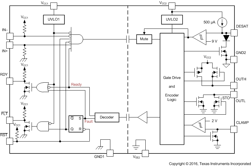
ISO5852S-Q1 FBD_SLLSEQ0.gif

4 修订历史记录

日期 修订版本 注释
2016 年 9 月 * 最初发布。

5 说明 (续)

内置的去饱和 (DESAT) 故障检测功能可识别 IGBT 何时处于过流状态。检测到 DESAT 时,静音逻辑会立即阻断隔离器输出,并启动软关断过程以禁用 OUTH 引脚并将 OUTL 引脚拉至低电平持续 2μs。当 OUTL 引脚达到 2V 时(相对于最大负电源电势 VEE2),栅极驱动器会被“硬”拉至 VEE2 电势,从而立即将 IGBT 关断。已将中的文本由“并降低 OUTL 的电压持续 2μs 以上”更改为“并将 OUTL 拉至低电平持续 2μs”

当发生去饱和故障时,器件会通过隔离隔栅发送故障信号,以将输入端的 FLT 输出拉为低电平并阻断隔离器的输入。静音逻辑在软关断期间激活。FLT 的输出状态将被锁存,并只能在 RDY 引脚变为高电平后通过 RST 输入上的低电平有效脉冲复位。已更改的第 3 段

如果在由双极输出电源供电的正常运行期间关断 IGBT,输出电压会被硬钳位为 VEE2。如果输出电源为单极,那么可采用有源米勒钳位,这种钳位会在一条低阻抗路径上灌入米勒电流,从而防止 IGBT 在高电压瞬态状态下发生动态导通。

栅极驱动器是否准备就绪待运行由两个欠压锁定电路控制,这两个电路会监视输入端和输出端的电源。如果任意一端电源不足,RDY 输出会变为低电平,否则该输出为高电平。

ISO5852S-Q1 采用 16 引脚小外形尺寸集成电路 (SOIC) 封装. 此器件的额定工作环境温度范围为 -40°C 至 +125°C。

6 Pin Configuration and Function

DW Package
16-Pin SOIC
Top View

Pin Functions

PIN I/O DESCRIPTION
NAME NO.
CLAMP 7 O Miller clamp output
DESAT 2 I Desaturation voltage input
FLT 13 O Fault output, active-low during DESAT condition
GND1 9 — Input ground
16
GND2 3 — Gate drive common. Connect to IGBT emitter.
IN+ 10 I Non-inverting gate drive voltage control input
IN– 11 I Inverting gate drive voltage control input
OUTH 4 O Positive gate drive voltage output
OUTL 6 O Negative gate drive voltage output
RDY 12 O Power-good output, active high when both supplies are good.
RST 14 I Reset input, apply a low pulse to reset fault latch.
VCC1 15 — Positive input supply (2.25-V to 5.5-V)
VCC2 5 — Most positive output supply potential.
VEE2 1 — Output negative supply. Connect to GND2 for unipolar supply application.
8

7 Specifications

7.1 Absolute Maximum Ratings

Over operating free-air temperature range (unless otherwise noted)(1)
MIN MAX UNIT
VCC1 Supply-voltage input side GND1 – 0.3 6 V
VCC2 Positive supply-voltage output side (VCC2 – GND2) –0.3 35 V
VEE2 Negative supply-voltage output side (VEE2 – GND2) –17.5 0.3 V
V(SUP2) Total-supply output voltage (VCC2 - VEE2) –0.3 35 V
V(OUTH) Positive gate-driver output voltage VEE2 – 0.3 VCC2 + 0.3 V
V(OUTL) Negative gate-driver output voltage VEE2 – 0.3 VCC2 + 0.3 V
I(OUTH) Gate-driver high output current Maximum pulse width = 10 μs, Maximum duty cycle = 0.2%) 2.7 A
I(OUTL) Gate-driver low output current Maximum pulse width = 10 μs, Maximum duty cycle = 0.2%) 5.5 A
V(LIP) Voltage at IN+, IN–,FLT, RDY, RST GND1 – 0.3 VCC1 + 0.3 V
I(LOP) Output current of FLT, RDY 10 mA
V(DESAT) Voltage at DESAT GND2 – 0.3 VCC2 + 0.3 V
V(CLAMP) Clamp voltage VEE2 – 0.3 VCC2 + 0.3 V
TJ Junction temperature –40 150 °C
TSTG Storage temperature –65 150 °C
(1) Stresses beyond those listed under Absolute Maximum Ratings may cause permanent damage to the device. These are stress ratings only, which do not imply functional operation of the device at these or any other conditions beyond those indicated under Recommended Operating Conditions. Exposure to absolute-maximum-rated conditions for extended periods may affect device reliability.

7.2 ESD Ratings

VALUE UNIT
V(ESD) Electrostatic discharge Human-body model (HBM), per AEC Q100-002(1) ±4000 V
Charged-device model (CDM), per AEC Q100-011 ±1500
(1) AEC Q100-002 indicates that HBM stressing shall be in accordance with the ANSI/ESDA/JEDEC JS-001 specification.

7.3 Recommended Operating Conditions

over operating free-air temperature range (unless otherwise noted)
MIN NOM MAX UNIT
VCC1 Supply-voltage input side 2.25 5.5 V
VCC2 Positive supply-voltage output side (VCC2 – GND2) 15 30 V
V(EE2) Negative supply-voltage output side (VEE2 – GND2) –15 0 V
V(SUP2) Total supply-voltage output side (VCC2 – VEE2) 15 30 V
V(IH) High-level input voltage (IN+, IN–, RST) 0.7 × VCC1 VCC1 V
V(IL) Low-level input voltage (IN+, IN–, RST) 0 0.3 × VCC1 V
tUI Pulse width at IN+, IN– for full output (CLOAD = 1 nF) 40 ns
tRST Pulse width at RST for resetting fault latch 800 ns
TA Ambient temperature –40 125 °C

7.4 Thermal Information

THERMAL METRIC(1) ISO5852S-Q1 UNIT
DW (SOIC)
16 PINS
RθJA Junction-to-ambient thermal resistance 99.6 °C/W
RθJC(top) Junction-to-case (top) thermal resistance 48.5 °C/W
RθJB Junction-to-board thermal resistance 56.5 °C/W
ψJT Junction-to-top characterization parameter 29.2 °C/W
ψJB Junction-to-board characterization parameter 56.5 °C/W
(1) For more information about traditional and new thermal metrics, see the Semiconductor and IC Package Thermal Metrics application report.

7.5 Power Ratings

Full-chip power dissipation is derated 10.04 mW/°C beyond 25°C ambient temperature. At 125°C ambient temperature, a maximum of 251 mW total power dissipation is allowed. Power dissipation can be optimized depending on ambient temperature and board design, while ensuring that the junction temperature does not exceed 150°C.
PARAMETER TEST CONDITIONS MIN TYP MAX UNIT
PD Maximum power dissipation (both sides) VCC1 = 5.5-V, VCC2 = 30-V, TA = 25°C 1255 mW
PID Maximum input power dissipation VCC1 = 5.5-V, VCC2 = 30-V, TA = 25°C 175 mW
POD Maximum output power dissipation VCC1 = 5.5-V, VCC2 = 30-V, TA = 25°C 1080 mW

7.6 Insulation Specifications

PARAMETER TEST CONDITIONS VALUE UNIT
GENERAL
CLR External clearance(1) Shortest terminal-to-terminal distance through air 8 mm
CPG External creepage(1) Shortest terminal-to-terminal distance across the package surface 8 mm
DTI Distance through the insulation Minimum internal gap (internal clearance) 21 µm
CTI Comparative tracking index DIN EN 60112 (VDE 0303-11); IEC 60112; Material Group I according to IEC 60664-1; UL 746A >600 V
Material group I
Overvoltage Category Rated mains voltage ≤ 600 VRMS I-IV
Rated mains voltage ≤ 1000 VRMS I-III
DIN V VDE V 0884-10 (VDE V 0884-10):2006-12(2)
VIORM Maximum repetitive peak isolation voltage AC voltage (bipolar) 2121 VPK
VIOWM Maximum isolation working voltage AC voltage (sine wave) Time dependent dielectric breakdown (TDDB) test, see Figure 1 1500 VRMS
DC voltage 2121 VDC
VIOTM Maximum transient isolation voltage VTEST = VIOTM; t = 60 s (qualification); t = 1 s (100% production) 8000 VPK
VIOSM Maximum surge isolation voltage(3) Test method per IEC 60065, 1.2/50 µs waveform, VTEST = 1.6 × VIOSM = 12800 VPK (qualification) 8000
qpd Apparent charge(4) Method a: After I/O safety test subgroup 2/3,
Vini = VIOTM, tini = 60 s;
Vpd(m) = 1.2 × VIORM = 2545 VPK ,
tm = 10 s
≤5 pC
Method a: After environmental tests subgroup 1,
Vini = VIOTM, tini = 60 s;
Vpd(m) = 1.6 × VIORM = 3394 VPK ,
tm = 10 s
≤5
Method b1: At routine test (100% production) and preconditioning (type test)
Vini = VIOTM, tini = 60 s;
Vpd(m) = 1.875× VIORM = 3977 VPK ,
tm = 10 s
≤5
CIO Barrier capacitance, input to output(5) VIO = 0.4 sin (2πft), f = 1 MHz 1 pF
RIO Isolation resistance, input to output(5) VIO = 500 V, TA = 25°C > 1012 Ω
VIO = 500 V, 100°C ≤ TA ≤ 125°C > 1011
VIO = 500 V at TS = 150°C > 109
Pollution degree 2
Climatic category
UL 1577
VISO Withstand isolation voltage VTEST = VISO = 5700 VRMS, t = 60 s (qualification); VTEST = 1.2 × VISO = 6840 VRMS, t = 1 s (100% production) 5700 VRMS
(1) Creepage and clearance requirements should be applied according to the specific equipment isolation standards of an application. Care should be taken to maintain the creepage and clearance distance of a board design to ensure that the mounting pads of the isolator on the printed-circuit board do not reduce this distance. Creepage and clearance on a printed-circuit board become equal in certain cases. Techniques such as inserting grooves and/or ribs on a printed circuit board are used to help increase these specifications.
(2) This coupler is suitable for safe electrical insulation only within the maximum operating ratings. Compliance with the safety ratings shall be ensured by means of suitable protective circuits.
(3) Testing is carried out in air or oil to determine the intrinsic surge immunity of the isolation barrier.
(4) Apparent charge is electrical discharge caused by a partial discharge (pd).
(5) All pins on each side of the barrier tied together creating a two-terminal device

7.7 Safety Limiting Values

Safety limiting intends to minimize potential damage to the isolation barrier upon failure of input or output circuitry. A failure of the I/O can allow low resistance to ground or the supply and, without current limiting, dissipate sufficient power to overheat the die and damage the isolation barrier, potentially leading to secondary system failures.
PARAMETER TEST CONDITIONS MIN TYP MAX UNIT
IS Safety input, output, or supply current RθJA = 99.6°C/W, VI = 2.75 V, TJ = 150°C, TA = 25°C, see Figure 2 456 mA
RθJA = 99.6°C/W, VI = 3.6 V, TJ = 150°C, TA = 25°C, see Figure 2 346
RθJA = 99.6°C/W, VI = 5.5 V, TJ = 150°C, TA = 25°C, see Figure 2 228
RθJA = 99.6°C/W, VI = 15 V, TJ = 150°C, TA = 25°C, see Figure 2 84
RθJA = 99.6°C/W, VI = 30 V, TJ = 150°C, TA = 25°C, see Figure 2 42
PS Safety input, output, or total power RθJA = 99.6°C/W, TJ = 150°C, TA = 25°C, see Figure 3 255(1) mW
TS Maximum ambient safety temperature 150 °C
(1) Input, output, or the sum of input and output power should not exceed this value

The safety-limiting constraint is the maximum junction temperature specified in the data sheet. The power dissipation and junction-to-air thermal impedance of the device installed in the application hardware determines the junction temperature. The assumed junction-to-air thermal resistance in the Thermal Information table is that of a device installed on a high-K test board for leaded surface-mount packages. The power is the recommended maximum input voltage times the current. The junction temperature is then the ambient temperature plus the power times the junction-to-air thermal resistance.

7.8 Safety-Related Certifications

VDE CSA UL CQC TUV
Certified according to DIN V VDE V 0884-10
(VDE V 0884-10):2006-12 and DIN EN 61010-1 (VDE 0411-1):2011-07
Plan to certify under CSA Component Acceptance Notice 5A, IEC 60950-1, and IEC 60601-1 Recognized under UL 1577 Component Recognition Program Certified according to GB4943.1-2011 Certified according to
EN 61010-1:2010 (3rd Ed) and
EN 60950-1:2006/A11:2009/A1:2010/
A12:2011/A2:2013
Reinforced Insulation Maximum Transient isolation voltage, 8000 VPK;
Maximum surge isolation voltage, 8000 VPK,
Maximum repetitive peak isolation voltage, 2121 VPK
Isolation Rating of 5700 VRMS;
Reinforced insulation per CSA 60950-1- 07+A1+A2 and IEC 60950-1 (2nd Ed.), 800 VRMS max working voltage (pollution degree 2, material group I) ;

2 MOPP (Means of Patient Protection) per CSA 60601-1:14 and IEC 60601-1 Ed. 3.1, 250 VRMS (354 VPK) max working voltage
Single Protection, 5700 VRMS (1) Reinforced Insulation, Altitude ≤ 5000m, Tropical climate, 400 VRMS maximum working voltage 5700 VRMS Reinforced insulation per
EN 61010-1:2010 (3rd Ed) up to working voltage of 600 VRMS

5700 VRMS Reinforced insulation per
EN 60950-1:2006/A11:2009/A1:2010/
A12:2011/A2:2013 up to working voltage of 800 VRMS
Certification completed
Certificate number: 40040142
Certificate planned Certification completed
File number: E181974
Certification completed
Certificate number: CQC16001141761
Certification completed
Client ID number: 77311
(1) Production tested ≥ 6840 VRMS for 1 second in accordance with UL 1577.

7.9 Electrical Characteristics

Over recommended operating conditions unless otherwise noted. All typical values are at TA = 25°C, VCC1 = 5 V,
VCC2 – GND2 = 15 V, GND2 – VEE2 = 8 V
PARAMETER TEST CONDITIONS MIN TYP MAX UNIT
VOLTAGE SUPPLY
VIT+(UVLO1) Positive-going UVLO1 threshold-voltage input side (VCC1 – GND1) 2.25 V
VIT-(UVLO1) Negative-going UVLO1 threshold-voltage input side (VCC1 – GND1) 1.7 V
VHYS(UVLO1) UVLO1 Hysteresis voltage (VIT+ – VIT–) input side 0.2 V
VIT+(UVLO2) Positive-going UVLO2 threshold-voltage output side (VCC2 – GND2) 12 13 V
VIT–(UVLO2) Negative-going UVLO2 threshold-voltage output side (VCC2 – GND2) 9.5 11 V
VHYS(UVLO2) UVLO2 hysteresis voltage (VIT+ – VIT–) output side 1 V
IQ1 Input-supply quiescent current 2.8 4.5 mA
IQ2 Output-supply quiescent current 3.6 6 mA
LOGIC I/O
VIT+(IN,RST) Positive-going input-threshold voltage (IN+, IN–, RST) 0.7 × VCC1 V
VIT–(IN,RST) Negative-going input-threshold voltage (IN+, IN–, RST) 0.3 × VCC1 V
VHYS(IN,RST) Input hysteresis voltage (IN+, IN–, RST) 0.15 × VCC1 V
IIH High-level input leakage at (IN+)(1) IN+ = VCC1 100 µA
IIL Low-level input leakage at (IN–, RST)(2) IN– = GND1, RST = GND1 -100 µA
IPU Pullup current of FLT, RDY V(RDY) = GND1, V(FLT) = GND1 100 µA
V(OL) Low-level output voltage at FLT, RDY I(FLT) = 5 mA 0.2 V
GATE DRIVER STAGE
V(OUTPD) Active output pulldown voltage I(OUTH/L) = 200 mA, VCC2 = open 2 V
VOUTH High-level output voltage I(OUTH) = –20 mA VCC2 – 0.5 VCC2 – 0.24 V
VOUTL Low-level output voltage I(OUTL) = 20 mA VEE2 + 13 VEE2 + 50 mV
I(OUTH) High-level output peak current IN+ = high, IN– = low,
V(OUTH) = VCC2 - 15 V
1.5 2.5 A
I(OUTL) Low-level output peak current IN+ = low, IN– = high,
V(OUTL) = VEE2 + 15 V
3.4 5 A
I(OLF) Low-level output current during fault condition 130 mA
ACTIVE MILLER CLAMP
V(CLP) Low-level clamp voltage I(CLP) = 20 mA VEE2 + 0.015 VEE2 + 0.08 V
I(CLP) Low-level clamp current V(CLAMP) = VEE2 + 2.5 V 1.6 2.5 3.3 A
V(CLTH) Clamp threshold voltage 1.6 2.1 2.5 V
SHORT CIRCUIT CLAMPING
V(CLP-OUTH) Clamping voltage
(VOUTH – VCC2)
IN+ = high, IN– = low, tCLP = 10 µs, I(OUTH) = 500 mA 1.1 1.3 V
V(CLP-OUTL) Clamping voltage
(VOUTL – VCC2)
IN+ = high, IN– = low, tCLP = 10 µs, I(OUTL) = 500 mA 1.3 1.5 V
V(CLP-CLP) Clamping voltage
(VCLP – VCC2)
IN+ = high, IN– = low, tCLP = 10 µs, I(CLP) = 500 mA 1.3 V
V(CLP-CLAMP) Clamping voltage at CLAMP IN+ = High, IN– = Low, I(CLP) = 20 mA 0.7 1.1 V
V(CLP-OUTL) Clamping voltage at OUTL
(VCLP – VCC2)
IN+ = High, IN– = Low, I(OUTL) = 20 mA 0.7 1.1 V
DESAT PROTECTION
I(CHG) Blanking-capacitor charge current V(DESAT) – GND2 = 2 V 0.42 0.5 0.58 mA
I(DCHG) Blanking-capacitor discharge current V(DESAT) – GND2 = 6 V 9 14 mA
V(DSTH) DESAT threshold voltage with respect to GND2 8.3 9 9.5 V
V(DSL) DESAT voltage with respect to GND2, when OUTH or OUTL is driven low 0.4 1 V
(1) IIH for IN–, RST pin is zero as they are pulled high internally
(2) IIL for IN+ is zero, as it is pulled low internally

7.10 Switching Characteristics

Over recommended operating conditions unless otherwise noted. All typical values are at TA = 25°C, VCC1 = 5 V,
VCC2 – GND2 = 15 V, GND2 – VEE2 = 8 V
PARAMETER TEST CONDITIONS MIN TYP MAX UNIT
tr Output-signal rise time at OUTH CLOAD = 1 nF See Figure 44, Figure 45, and Figure 46 12 18 35 ns
tf Output-signal fall time at OUTL CLOAD = 1 nF 12 20 37 ns
tPLH, tPHL Propagation Delay CLOAD = 1 nF 76 110 ns
tsk-p Pulse skew |tPHL – tPLH| CLOAD = 1 nF 20 ns
tsk-pp Part-to-part skew CLOAD = 1 nF 30(1) ns
tGF (IN,/RST) Glitch filter on IN+, IN–, RST CLOAD = 1 nF 20 30 40 ns
tDS (90%) DESAT sense to 90% VOUTH/L delay CLOAD = 10 nF 553 760 ns
tDS (10%) DESAT sense to 10% VOUTH/L delay CLOAD = 10 nF 2 3.5 μs
tDS (GF) DESAT-glitch filter delay CLOAD = 1 nF 330 ns
tDS (FLT) DESAT sense to FLT-low delay See Figure 46 1.4 μs
tLEB Leading-edge blanking time See Figure 44 and Figure 45 310 400 480 ns
tGF(RSTFLT) Glitch filter on RST for resetting FLT 300 800 ns
CI Input capacitance(2) VI = VCC1 / 2 + 0.4 × sin (2πft), f = 1 MHz, VCC1 = 5 V 2 pF
CMTI Common-mode transient immunity VCM = 1500 V, see Figure 47 100 120 kV/μs
(1) Measured at same supply voltage and temperature condition
(2) Measured from input pin to ground.

7.11 Safety and Insulation Characteristics Curves

ISO5852S-Q1 tddb_curve_reinforced_dw.gif
TA upto 150°C Stress-voltage frequency = 60 Hz
Figure 1. Reinforced High-Voltage Capacitor Lifetime Projection
ISO5852S-Q1 D100_SLLSEQ0.gif Figure 2. Thermal Derating Curve for Safety Limiting Current per VDE
ISO5852S-Q1 D101_SLLSEQ0.gif Figure 3. Thermal Derating Curve for Safety Limiting Power per VDE

7.12 Typical Characteristics

ISO5852S-Q1 D001_SLLSEQ0.gif
Figure 4. Output High Drive Current vs Temperature
ISO5852S-Q1 D002_SLLSEQ0.gif
Figure 6. Output Low Drive Current vs Temperature
ISO5852S-Q1 D005_SLLSEQ0.gif
Unipolar: VCC2 – VEE2 = VCC2 – GND2
Figure 8. DESAT Threshold Voltage vs Temperature
ISO5852S-Q1 D003_SLLSEQ0.gif
Figure 5. Output High Drive Current vs Output Voltage
ISO5852S-Q1 D004_SLLSEQ0.gif
Figure 7. Output Low Drive Current vs Output Voltage
ISO5852S-Q1 G010_SLLSEQ0.gif
CL = 1 nF RGH = 0 Ω RGL = 0 Ω
VCC2 – VEE2 = VCC2 – GND2 = 20 V
Figure 9. Output Transient Waveform
ISO5852S-Q1 G002_SLLSEQ0.gif
CL = 100 nF RGH = 0 Ω RGL = 0 Ω
VCC2 – VEE2 = VCC2 – GND2 = 20 V
Figure 11. Output Transient Waveform
ISO5852S-Q1 G004_SLLSEQ0.gif
CL = 10 nF RGH = 10 Ω RGL = 5 Ω
VCC2 – VEE2 = VCC2 – GND2 = 20 V
Figure 13. Output Transient Waveform
ISO5852S-Q1 Figure12_Out_Tranfer_Wave_FLT_SLLSEQ0.gif
CL = 10 nF RGH = 0 Ω RGL = 0 Ω
VCC2 – VEE2 = VCC2 – GND2 = 15 V DESAT = 220 pF
Figure 15. Output Transient Waveform DESAT, RDY, and FLT
ISO5852S-Q1 G006_SLLSEQ0.gif
CL = 10 nF RGH = 0 Ω RGL = 0 Ω
VCC2 – VEE2 = VCC2 – GND2 = 30 V DESAT = 220 pF
Figure 17. Output Transient Waveform DESAT, RDY, and FLT
ISO5852S-Q1 D006_SLLSEQ0.gif
IN+ = High IN– = Low
Figure 19. ICC1 Supply Current vs Temperature
ISO5852S-Q1 D008_SLLSEQ0.gif
Figure 21. ICC1 Supply Current vs Input Frequency
ISO5852S-Q1 D009_SLLSEQ0.gif
No CL
Figure 23. ICC2 Supply Current vs Input Frequency
ISO5852S-Q1 D012_SLLSEQ0.gif
CL = 1 nF RGH = 0 Ω RGL = 0 Ω
VCC1 = 5 V
Figure 25. Propagation Delay vs Temperature
ISO5852S-Q1 D014_SLLSEQ0.gif
RGH = 10 Ω RGL = 5 Ω VCC1 = 5 V
Figure 27. Propagation Delay vs Load Capacitance
ISO5852S-Q1 D016_SLLSEQ0.gif
RGH = 0 Ω RGL = 0 Ω VCC1 = 5 V
Figure 29. tf Fall Time v. Load Capacitance
ISO5852S-Q1 D018_SLLSEQ0.gif
RGH = 10 Ω RGL = 5 Ω VCC1 = 5 V
Figure 31. tf Fall Time vs Load Capacitance
ISO5852S-Q1 D020_SLLSEQ0.gif
CL = 10 nF RGH = 0 Ω RGL = 0 Ω
Figure 33. DESAT Sense to VOUT 10% Delay vs Temperature
ISO5852S-Q1 D022_SLLSEQ0.gif
Figure 35. DESAT Sense to Fault Low Delay vs Temperature
ISO5852S-Q1 D023_SLLSEQ0.gif
Figure 37. Reset to Fault Delay Across Temperature
ISO5852S-Q1 D026_SLLSEQ0.gif
Figure 39. Active Pulldown Voltage vs Temperature
ISO5852S-Q1 D027_SLLSEQ2.gif
Figure 41. VOUTH_CLAMP - Short-Circuit Clamp Voltage on OUTH Across Temperature
ISO5852S-Q1 D030_SLLSEQ0.gif
VCC2 = 15 V DESAT = 6 V
Figure 43. Blanking Capacitor Charging Current vs Temperature
ISO5852S-Q1 G001_SLLSEQ0.gif
CL = 10 nF RGH = 0 Ω RGL = 0 Ω
VCC2 – VEE2 = VCC2 – GND2 = 20 V
Figure 10. Output Transient Waveform
ISO5852S-Q1 G003_SLLSEQ0.gif
CL = 1 nF RGH = 10 Ω RGL = 5 Ω
VCC2 – VEE2 = VCC2 – GND2 = 20 V
Figure 12. Output Transient Waveform
ISO5852S-Q1 G005_SLLSEQ0.gif
CL = 100 nF RGH = 10 Ω RGL = 5 Ω
VCC2 – VEE2 = VCC2 – GND2 = 20 V
Figure 14. Output Transient Waveform
ISO5852S-Q1 G007_SLLSEQ0.gif
CL = 10 nF RGH = 0 Ω RGL = 0 Ω
VCC2 – VEE2 = VCC2 – GND2 = 15 V DESAT = 220 pF
Figure 16. Output Transient Waveform DESAT, RDY, and FLT
ISO5852S-Q1 G008_SLLSEQ0.gif
CL = 10 nF RGH = 0 Ω RGL = 0 Ω
VCC2 – VEE2 = VCC2 – GND2 = 30 V DESAT = 220 pF
Figure 18. Output Transient Waveform DESAT, RDY, and FLT
ISO5852S-Q1 D007_SLLSEQ0.gif
IN+ = Low IN– = Low
Figure 20. ICC1 Supply Current vs Temperature
ISO5852S-Q1 D010_SLLSEQ0.gif
Input frequency = 1 kHz
Figure 22. ICC2 Supply Current vs Temperature
ISO5852S-Q1 D011_SLLSEQ0.gif
RGH = 10 Ω RGL = 5 Ω, 20 kHz
Figure 24. ICC2 Supply Current vs Load Capacitance
ISO5852S-Q1 D013_SLLSEQ0.gif
CL = 1 nF RGH = 0 Ω RGL = 0 Ω
VCC2 = 15 V
Figure 26. Propagation Delay vs Temperature
ISO5852S-Q1 D015_SLLSEQ0.gif
RGH = 0 Ω RGL = 0 Ω VCC1 = 5 V
Figure 28. tr Rise Time vs Load Capacitance
ISO5852S-Q1 D017_SLLSEQ0.gif
RGH = 10 Ω RGL = 5 Ω VCC1 = 5 V
Figure 30. tr Rise Time vs Load Capacitance
ISO5852S-Q1 D019_SLLSEQ0.gif
Figure 32. Leading Edge Blanking Time With Temperature
ISO5852S-Q1 D021_SLLSEQ0.gif
CL = 10 nF RGH = 0 Ω RGL = 0 Ω
Figure 34. DESAT Sense to VOUT 90% Delay vs Temperature
ISO5852S-Q1 D024_SLLSEQ0.gif
Figure 36. Fault and RDY Low to RDY High Delay vs Temperature
ISO5852S-Q1 D025_SLLSEQ0.gif
Figure 38. Miller Clamp Current vs Temperature
ISO5852S-Q1 D029_SLLSEQ2.gif
Figure 40. VCLP_CLAMP - Short-Circuit Clamp Voltage on Clamp Across Temperature
ISO5852S-Q1 D028_SLLSEQ2.gif
Figure 42. VOUTL_CLAMP - Short-Circuit Clamp Voltage on OUTL Across Temperature

8 Parameter Measurement Information

ISO5852S-Q1 Propagation_Delay_NonInverting_Configuration_SLLSEQ0.gif Figure 44. OUTH and OUTL Propagation Delay, Non-Inverting Configuration
ISO5852S-Q1 Propagation_Delay_Inverting_Configuration_SLLSEQ0.gif Figure 45. OUTH and OUTL Propagation Delay, Inverting Configuration
ISO5852S-Q1 DESAT_OUT_FLT_RST_Delay_SLLSEQ0.gif Figure 46. DESAT, OUTH/L, FLT, RST Delay
ISO5852S-Q1 CMTI_test_circuit_SLLSEQ0.gif Figure 47. Common-Mode Transient Immunity Test Circuit

9 Detailed Description

9.1 Overview

The ISO5852S-Q1 is an isolated gate driver for IGBTs and MOSFETs. Input CMOS logic and output power stage are separated by a Silicon dioxide (SiO2) capacitive isolation.

The IO circuitry on the input side interfaces with a micro controller and consists of gate drive control and RESET (RST) inputs, READY (RDY) and FAULT (FLT) alarm outputs. The power stage consists of power transistors to supply 2.5-A pullup and 5-A pulldown currents to drive the capacitive load of the external power transistors, as well as DESAT detection circuitry to monitor IGBT collector-emitter overvoltage under short circuit events. The capacitive isolation core consists of transmit circuitry to couple signals across the capacitive isolation barrier, and receive circuitry to convert the resulting low-swing signals into CMOS levels. The ISO5852S-Q1 also contains under voltage lockout circuitry to prevent insufficient gate drive to the external IGBT, and active output pulldown feature which ensures that the gate-driver output is held low, if the output supply voltage is absent. The ISO5852S-Q1 also has an active Miller clamp function which can be used to prevent parasitic turn-on of the external power transistor, due to Miller effect, for unipolar supply operation.

9.2 Functional Block Diagram

ISO5852S-Q1 FBD_SLLSEQ0.gif

9.3 Feature Description

9.3.1 Supply and Active Miller clamp

The ISO5852S-Q1 supports both bipolar and unipolar power supply with active Miller clamp.

For operation with bipolar supplies, the IGBT is turned off with a negative voltage on its gate with respect to its emitter. This prevents the IGBT from unintentionally turning on because of current induced from its collector to its gate due to Miller effect. In this condition it is not necessary to connect CLAMP output of the gate driver to the IGBT gate, but connecting CLAMP output of the gate driver to the IGBT gate is also not an issue. Typical values of VCC2 and VEE2 for bipolar operation are 15-V and -8-V with respect to GND2.

For operation with unipolar supply, typically, VCC2 is connected to 15-V with respect to GND2, and VEE2 is connected to GND2. In this use case, the IGBT can turn on due to additional charge from IGBT Miller capacitance caused by a high voltage slew rate transition on the IGBT collector. To prevent IGBT to turn on, the CLAMP pin is connected to IGBT gate and Miller current is sinked through a low impedance CLAMP transistor.

Miller CLAMP is designed for Miller current up to 2-A. When the IGBT is turned-off and the gate voltage transitions below 2-V the CLAMP current output is activated.

9.3.2 Active Output Pulldown

The Active output pulldown feature ensures that the IGBT gate OUTH/L is clamped to VEE2 to ensure safe IGBT off-state, when the output side is not connected to the power supply.

9.3.3 Undervoltage Lockout (UVLO) With Ready (RDY) Pin Indication Output

Undervoltage Lockout (UVLO) ensures correct switching of IGBT. The IGBT is turned-off, if the supply VCC1 drops below VIT-(UVLO1), irrespective of IN+, IN– and RST input till VCC1 goes above VIT+(UVLO1).

In similar manner, the IGBT is turned-off, if the supply VCC2 drops below VIT-(UVLO2), irrespective of IN+, IN– and RST input till VCC2 goes above VIT+(UVLO2).

Ready (RDY) pin indicates status of input and output side Under Voltage Lock-Out (UVLO) internal protection feature. If either side of device have insufficient supply (VCC1 or VCC2), the RDY pin output goes low; otherwise, RDY pin output is high. RDY pin also serves as an indication to the micro-controller that the device is ready for operation.

9.3.4 Soft Turnoff, Fault (FLT) and Reset (RST)

During IGBT overcurrent condition, a mute logic initiates a soft-turn-off procedure which disables, OUTH, and pulls OUTL to low over a time span of 2 μs. When desaturation is active, a fault signal is sent across the isolation barrier pulling the FLT output at the input side low and blocking the isolator input. mute logic is activated through the soft-turn-off period. The FLT output condition is latched and can be reset only after RDY goes high, through a active-low pulse at the RST input. RST has an internal filter to reject noise and glitches. By asserting RST for at-least the specified minimum duration (800 ns), device input logic can be enabled or disabled.

9.3.5 Short Circuit Clamp

Under short circuit events it is possible that currents are induced back into the gate-driver OUTH/L and CLAMP pins due to parasitic Miller capacitance between the IGBT collector and gate terminals. Internal protection diodes on OUTH/L and CLAMP help to sink these currents while clamping the voltages on these pins to values slightly higher than the output side supply.

9.4 Device Functional Modes

In ISO5852S-Q1 OUTH/L to follow IN+ in normal functional mode, FLT pin must be in the high state. Table 1 lists the device functions.

Table 1. Function Table(1)

VCC1 VCC2 IN+ IN– RST RDY OUTH/L
PU PD X X X Low Low
PD PU X X X Low Low
PU PU X X Low High Low
PU Open X X X Low Low
PU PU Low X X High Low
PU PU X High X High Low
PU PU High Low High High High
(1) PU: Power Up (VCC1 ≥ 2.25 V, VCC2 ≥ 13 V), PD: Power Down (VCC1 ≤ 1.7 V, VCC2 ≤ 9.5 V), X: Irrelevant


Texas Instruments

© Copyright 1995-2025 Texas Instruments Incorporated. All rights reserved.
Submit documentation feedback | IMPORTANT NOTICE | Trademarks | Privacy policy | Cookie policy | Terms of use | Terms of sale