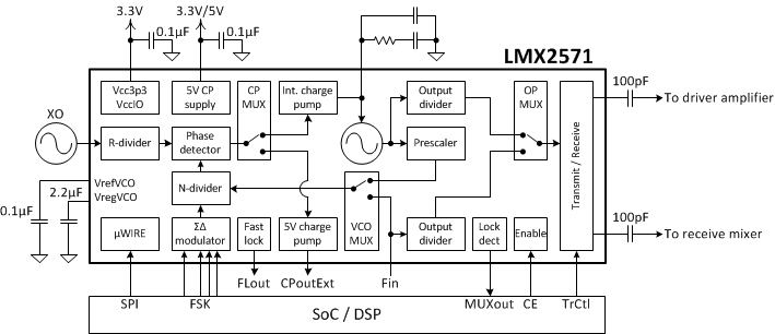
LMX2571 是一款低功耗、高性能、宽带 PLLatinum™ 射频 (RF) 合成器,该合成器集成了 Δ-Σ 分数 N PLL、多核压控振荡器 (VCO)、可编程输出分压器以及两个输出缓冲器。 VCO 内核的工作频率高达 5.376GHz,持续输出频率范围为 10MHz 至 1344MHz。
该合成器还可搭配外部 VCO 使用。 在此配置下,需使用专用的 5V 电荷泵和输出分压器。
该合成器还包含一个独特的可编程乘法器,有助于去除毛刺,即使毛刺落在整数边界,系统也仍能够使用任一通道。
其输出具有 SPDT 开关,可用作 FDD 无线电应用中的发送/接收开关。 并且可同时导通两个开关,以便同时提供双输出。
LMX2571 通过编程或相应引脚来支持直接数字 FSK 调制。 该器件支持离散电平 FSK、脉冲成形 FSK 以及模拟 FM 调制。
该器件采用了一项全新的 FastLock 技术,即使在外部 VCO 与窄带回路滤波器搭配使用时,用户也能够在不到 1.5ms 的时间内从一个频率切换至另一频率。
器件型号 | 封装 | 封装尺寸(标称值) |
---|---|---|
LMX2571 | WQFN (36) | 6.00mm x 6.00mm |
日期 | 修订版本 | 注释 |
---|---|---|
2015 年 3 月 | * | 最初发布。 |
PIN | TYPE | DESCRIPTION | |
---|---|---|---|
NAME | NO. | ||
Bypass1 | 2 | Bypass | Place a 100-nF capacitor to GND. |
Bypass2 | 3 | Bypass | Place a 100-nF capacitor to GND. |
CE | 19 | Input | Chip Enable input. Active HIGH powers on the device. |
CLK | 11 | Input | MICROWIRE clock input. |
CPout | 25 | Output | Internal VCO charge pump access point to connect to a 2nd order loop filter. |
CPoutExt | 30 | Output | 5-V charge pump output used in PLL mode (external VCO). |
DAP | 0 | GND | The DAP should be grounded. |
DATA | 12 | Input | MICROWIRE serial data input. |
Fin | 24 | Input | High frequency AC coupled input pin for an external VCO. Leave it open or AC coupled to GND if not being used. |
FSK_D0 | 7 | Input | FSK data bit 0 (FSK PIN mode) / I2S FS input (FSK I2S mode). |
FSK_D1 | 6 | Input | FSK data bit 1 (FSK PIN mode) / I2S DATA input (FSK I2S mode). |
FSK_D2 | 5 | Input | FSK data bit 2 (FSK PIN mode). |
FSK_DV | 4 | Input | FSK data valid input (FSK PIN mode) / I2S CLK input (FSK I2S mode). |
FLout1 | 29 | Output | FastLock output control 1 for external switch. Output is HIGH when F1 is selected. |
FLout2 | 28 | Output | FastLock output control 2 for external switch. Output is HIGH when F2 is selected. |
GND | 23 | GND | VCO ground. |
GND | 31 | GND | Charge pump ground. |
GND | 35 | GND | OSCin ground. |
LE | 13 | Input | MICROWIRE latch enable input. |
MUXout | 10 | Output | Multiplexed output that can be assigned to lock detect or readback serial data output. |
NC | 8,14, 26 | NC | Do not connect these pins. |
OSCin | 34 | Input | Reference clock input. |
OSCin* | 36 | Input | Complementary reference clock input. |
RFoutRx | 16 | Output | RF output used to drive receive mixer. Selectable open drain or push-pull output. |
RFoutTx | 17 | Output | RF output used to drive transmit signal. Selectable open drain or push-pull output. |
TrCtl | 18 | Input | Transmit/Receive control. This pin controls the RF output port and the output frequency selection. |
Vcc3p3 | 1, 9, 20, 27 | Supply | Connect to 3.3-V supply. |
VccIO | 15, 33 | Supply | Supply for digital logic interface. Connect to 3.3-V supply. |
VcpExt | 32 | Supply | Supply for 5-V charge pump. Connect to 5-V supply in PLL mode. Connect to either 3.3-V or 5-V supply in synthesizer mode. |
VrefVCO | 22 | Bypass | LDO output. Place a 100-nF capacitor to GND. |
VregVCO | 21 | Bypass | Bias circuitry for the VCO. Place a 2.2-µF capacitor to GND. |
MIN | MAX | UNIT | ||
---|---|---|---|---|
VCC | Power supply voltage | –0.3 | 3.6 | V |
VIO | IO supply voltage | –0.3 | 3.6 | V |
VIN | IO input voltage | VCC + 0.3 | V | |
VCP | Charge pump supply voltage | 5.25 | V | |
TJ | Junction temperature | 150 | °C | |
TSTG | Storage temperature | –65 | 150 | °C |
VALUE | UNIT | |||
---|---|---|---|---|
V(ESD) | Electrostatic discharge | Human-body model (HBM), per ANSI/ESDA/JEDEC JS-001(1) | ±1500 | V |
Charged-device model (CDM), per JEDEC specification JESD22-C101(2) | ±500 |
MIN | MAX | UNIT | |||
---|---|---|---|---|---|
VCC | Power supply voltage | 3.15 | 3.45 | V | |
VIO | IO supply voltage | VCC | V | ||
VCP | Charge pump supply voltage | PLL mode (external VCO) | 5 | V | |
Synthesizer mode (internal VCO) | VCC | 5 | |||
TA | Ambient temperature | –40 | 85 | °C | |
TJ | Junction Temperature | 125 | °C |
THERMAL METRIC(1) | LMX2571 | UNIT | |
---|---|---|---|
WQFN (NJK) | |||
36 PINS | |||
RθJA | Junction-to-ambient thermal resistance | 32.9 | °C/W |
RθJC(top) | Junction-to-case (top) thermal resistance | 14.5 | |
RθJB | Junction-to-board thermal resistance | 6.3 | |
ψJT | Junction-to-top characterization parameter | 0.2 | |
ψJB | Junction-to-board characterization parameter | 6.3 | |
RθJC(bot) | Junction-to-case (bottom) thermal resistance | 2.0 |
PARAMETER | TEST CONDITIONS | MIN | TYP | MAX | UNIT | ||
---|---|---|---|---|---|---|---|
CURRENT CONSUMPTION | |||||||
ICC | Total current in synthesizer mode (internal VCO) | fOUT = 480 MHz SE OSCin |
Configuration A(1) | 39 | mA | ||
Configuration B(2) | 44 | ||||||
Configuration C(3) | 46 | ||||||
Configuration D(4) | 51 | ||||||
IPLL | Total current in PLL mode (external VCO) | Configuration E(5) | 9 | ||||
Configuration F(6) | 15 | ||||||
Configuration G(7) | 21 | ||||||
ICCPD | Power down current | CE = 0V or POWERDOWN bit = 1 VCC = 3.3 V, Push-pull output |
0.9 | ||||
OSCIN REFERENCE INPUT | |||||||
fOSCin | OSCin frequency range | Single-ended or differential input | 10 | 150 | MHz | ||
VOSCin | OSCin input voltage(8) | Single-ended input | 1.4 | 3.3 | V | ||
Differential input | 0.15 | 1.5 | |||||
CRYSTAL REFERENCE INPUT | |||||||
fXTAL | Crystal frequency range | Fundamental model, ESR < 200 Ω | 10 | 40 | MHz | ||
CIN | OSCin input capacitance | 1 | pF | ||||
MULT | |||||||
fMULTin | MULT input frequency | MULT > Pre-divider Not supported with crystal reference input |
10 | 30 | MHz | ||
fMULTout | MULT output frequency | 60 | 130 | MHz | |||
PLL | |||||||
fPD | Phase detector frequency | 130 | MHz | ||||
KPD | Charge pump current(9) | Programmable minimum value | Internal charge pump | 312.5 | µA | ||
5-V charge pump | 625 | ||||||
Per programmable step | Internal charge pump | 312.5 | |||||
5-V charge pump | 625 | ||||||
Programmable maximum value | Internal charge pump | 7187.5 | |||||
5-V charge pump | 6875 | ||||||
PNPLL_1/f | Normalized PLL 1/f noise(10) | At maximum charge pump current | Internal charge pump | –124 | dBc/Hz | ||
5-V charge pump | –120 | ||||||
PNPLL_Flat | Normalized PLL noise floor(10) | Internal charge pump | –231 | dBc/Hz | |||
5-V charge pump | –226 | ||||||
fRFin | External VCO input frequency | 100 | 1400 | MHz | |||
PRFin | External VCO input power | fRFin < 1 GHz | –10 | dBm | |||
fRFin ≥ 1 GHz | –5 | ||||||
VCO | |||||||
fVCO | VCO frequency | 4300 | 5376 | MHz | |||
KVCO | VCO gain(11) | fVCO = 4800 MHz | 56 | MHz/V | |||
| ΔTCL | | Allowable temperature drift(12) | VCO not being re-calibrated, –40 °C ≤ TA ≤ 85 °C | 125 | °C | |||
tVCOCal | VCO calibration time | fOSCin = fPD = 100 MHz | 140 | µs | |||
PNVCO | Open loop VCO phase noise | fOUT = 480 MHz | 100 Hz offset | –32.4 | dBc/Hz | ||
1 kHz offset | –62.3 | ||||||
10 kHz offset | –92.1 | ||||||
100 kHz offset | –121.1 | ||||||
1 MHz offset | –144.5 | ||||||
10 MHz offset | –156.8 | ||||||
RF OUTPUT | |||||||
fOUT | RF output frequency | Synthesizer mode | 10 | 1344 | MHz | ||
PLL mode, RF output from buffer | 10 | 1400 | |||||
PTX, PRX | RF output power | fOUT = 480 MHz | Power control bit = 6 | 0 | dBm | ||
H2RFout | Second harmonic | –25 | dBc | ||||
DIGITAL FSK MODULATION | |||||||
FSKLevel | FSK level(13) | FSK PIN mode | 2 | 8 | |||
FSKBaud | FSK baud rate(14) | Loop bandwidth = 200 kHz | 100 | kSPs | |||
FSKDev | FSK deviation | Configuration H(15) | ±39 | kHz | |||
DIGITAL INTERFACE | |||||||
VIH | High level input voltage | 1.4 | VIO | V | |||
VIL | Low level input voltage | 0.4 | V | ||||
IIH | High level input current | VIH = 1.75 V | –25 | 25 | µA | ||
IIL | Low level input current | VIL = 0 V | –25 | 25 | µA | ||
VOH | High level output voltage | IOH = 500 µA | 2 | V | |||
VOL | Low level output voltage | IOL = –500 µA | 0 | 0.4 | V |
MIN | NOM | MAX | UNIT | |||
---|---|---|---|---|---|---|
MICROWIRE TIMING | ||||||
tES | Clock to enable low time | See Figure 1 | 5 | ns | ||
tCS | Data to clock setup time | 2 | ns | |||
tCH | Data to clock hold time | 2 | ns | |||
tCWH | Clock pulse width high | 5 | ns | |||
tCWL | Clock pulse width low | 5 | ns | |||
tCES | Enable to clock setup time | 5 | ns | |||
tEWH | Enable pulse width high | 2 | ns |
There are several other considerations for programming:
OSCin = 19.44 MHz | fOUT = 200 MHz | Synthesizer mode |
OSCin = 19.44 MHz | fOUT = 900 MHz | Synthesizer mode |
FSKBaud = 4.8 kSPS | FSK PIN mode |
Switching between int. and ext. VCO as well as Tx and Rx port |
Start: 100 MHz | Stop: 2000 MHz |
fOUT = 1228.8 MHz | fPD = 122.88 MHz | Synthesizer mode |
OSCin = 19.44 MHz | fOUT = 500 MHz | Synthesizer mode |
OSCin = 19.44 MHz | fOUT = 1200 MHz | Synthesizer mode |
Reference clock is a FM modulated signal with fMOD = 2.4 kHz |
Freq. jump = 50 MHz | LBW = 4 kHz | PLL mode |
Start: 10 MHz | Stop: 300 MHz |
fOUT = 430.08 MHz | fPD = 61.44 MHz | PLL mode |
The LMX2571 is a frequency synthesizer with low-noise, high-performance integrated VCOs. The 5-GHz VCO cores, together with the output channel dividers, can produce frequencies from 10 MHz to 1344 MHz. The LMX2571 supports two operation modes, synthesizer mode and PLL mode. In synthesizer mode, the entire device is utilized; in PLL mode the internal VCO is bypassed, and an external VCO is required to implement a complete synthesizer.
The reference clock input supports a crystal used for the on-chip oscillator, AC-coupled differential clock signals, and DC-coupled single-ended clock signals such as XO or CMOS clock devices.
The PLL is a fractional-N PLL with programmable Delta Sigma modulator (first order to fourth order). The fractional denominator is of variable length and up to 24-bits long, providing a frequency step with very fine resolution.
The internal VCO can be bypassed, allowing the use of an external VCO. A separate 5-V charge pump is dedicated for the external VCO, eliminating the need for an op-amp to support 5-V VCOs. A new advanced FastLock technique is developed to shorten the lock time to less than 1.5 ms, even there is a very narrow loop bandwidth.
A unique programmable multiplier is incorporated in the R-divider. The multiplier is used to avoid and reduce integer boundary spurs or to increase the phase detector frequency for higher performance.
The LMX2571 supports direct digital FSK modulation, thus allowing a change in the output frequency by changing the N-divider value. The N-divider value can be programmed through MICROWIRE interface or through pins. Discrete 2-, 4- and 8-level FSK, as well as arbitrary-level FSK, are supported. Arbitrary-level FSK can be used to construct pulse-shaping FSK or analog-FM modulation.
The output has an integrated T/R switch, and the divided-down internal or external VCO signal can be output to either the TX port or the RX port. The switch can also be configured as a 1:2 fanout buffer, providing the signal on both outputs at the same time. In addition to port switching, the output frequency can be switched between two pre-defined frequencies, F1 and F2, simultaneously. This feature is ideal for use in FDD duplex system where the TX frequency is different from RX (LO) frequency.
The LMX2571 requires only a single 3.3-V power supply. Digital logic interface is 1.8-V input compatible. The analog blocks power supplies use integrated LDOs, eliminating the need for high performance external LDOs.
Programming of the device is achieved through the MICROWIRE interface. The device can be powered down through a register programming or toggling the Chip Enable (CE) pin.
The OSCin and OSCin* pins are used as frequency reference inputs to the device. The OSCin pin can be driven single-ended with a CMOS clock or a crystal oscillator. The on-chip crystal oscillator can also be used with an external crystal as the reference clock. Differential clock input is also supported, making it easily to interface with high performance system clock devices such as TI’s LMK series clock devices.
Because the OSCin or OSCin* signal is used as a clock for VCO calibration, a proper signal needs to be applied at the OSCin and/or OSCin* pin at the time of programming the R0 register. A higher slew rate tends to yield the best fractional spurs and phase noise, so a square wave signal is best for the OSCin and/or OSCin*pins. If using a sine wave, higher frequencies tend to yield better phase noise and fractional spurs due to their higher slew rates.
The R-divider consists of a Pre-divider, a Multiplier (MULT), and a Post-divider.
Both the Pre- and Post-dividers divide frequency down while the MULT multiplies frequency up. The purpose of adding a multiplier is to avoid and reduce integer boundary spurs or to increase the phase-detector frequency for higher performance. See MULT Multiplier for details. The phase detector frequency, fPD, is therefore equal to
When using the Multiplier (MULT > 1), there are some points to remember:
The phase detector compares the outputs of the Post-divider and N-divider and generates a correction current corresponding to the phase error. This charge pump current is programmable to different strengths.
The total N-divider value is determined by Ninteger + NUM / DEN. The N-divider includes fractional compensation and can achieve any fractional denominator (DEN) from 1 to 16,777,215 (224 – 1). The integer portion, Ninteger, is the whole part of the N-divider value and the fractional portion, Nfrac = NUM / DEN, is the remaining fraction. Ninteger, NUM and DEN are programmable.
The order of the delta sigma modulator is also programmable from integer mode to fourth order. There are several dithering modes that are also programmable. Dithering is used to reduce fractional spurs. In order to make the fractional spurs consistent, the modulator is reset any time that the R0 register is programmed.
The LMX2571 integrates the third and fourth pole of the loop filter. The values for the resistors can be programmed independently through the MICROWIRE interface. The larger the values of the resistors, the stronger the attenuation of the internal loop filter. This partially integrated loop filter can only be used in synthesizer mode.
The LMX2571 includes a fully integrated VCO. The VCO generates a frequency which varies with the tuning voltage from the loop filter. Output of the VCO is fed to a prescaler before going to the N-divider. The prescaler value is selectable between 2 and 4. In general, prescaler equals 2 will result in better phase noise especially when the PLL is operated in fractional-N mode. If the prescaler equals 4, however, the device will consume less current. The VCO frequency is related to the other frequencies and Prescaler as follows:
In order to reduce the VCO tuning gain, thus improving the VCO phase noise performance, the VCO frequency range is divided into several different frequency bands. This creates the need for frequency calibration in order to determine the correct frequency band given a desired output frequency. The VCO is also calibrated for amplitude to optimize phase noise. These calibration routines are activated any time that the R0 register is programmed with the FCAL_EN bit equals one. It is important that a valid OSCin signal must present before VCO calibration begins.
This device will support a full sweep of the valid temperature range of 125°C (–40°C to 85°C) without having to re-calibrate the VCO. This is important for continuous operation of the synthesizer under the most extreme temperature variation.
The LMX2571 supports an external VCO in PLL mode. In PLL mode, the internal VCO and its associated charge pump are powered down, and a 5-V charge pump is switched in to support external VCO. No extra external low noise op-amp is required to support 5-V tuning range VCO. The external VCO output can be obtained directly from the VCO or from the device’s RF output buffer.
The internal VCO RF output divider consists of two sub-dividers; the total division value is equal to the multiplication of them. As a result, the minimum division is 4 while the maximum division is 448.
There is only one output divider when external VCO is being used. This divider supports even and odd division, and its values are programmable between 1 and 10.
The RF output buffer type is selectable between push-pull and open drain. If open drain buffer is selected, external pullup to VccIO is required. Regardless of output type, output power can be programmed to various levels. The RF output buffer can be disabled while still keeping the PLL in lock. See RF Output Buffer Type for details.
The LMX2571 integrates a T/R switch which is controlled by the TrCtl pin. The output from the internal VCO or external VCO divider will be routed to either the RFoutTx or RFoutRx ports, depending on the state of the TrCtl pin. The TrCtl pin not only controls the output port, but may also switch the output frequency simultaneously. For example, if TrCtl = 1, the active port is RFoutTx with an output frequency of F1. When TrCtl changes from 1 to 0, the active port could be RFoutRx with an output frequency of F2. LMX2571 has two sets of register to store the configurations for F1 and F2.
The T/R switch could also be configured as a fanout buffer to output the same signal at both RFoutTx and RFoutRx ports at the same time. All of these features are also programmable, see Programming and Frequency and Output Port Switching with TrCtl Pin for details.
The LMX2571 can be powered up and down using the CE pin or the POWERDOWN bit. All registers are preserved in memory while it is powered down. When the device comes out of the powered down state, either by resuming the POWERDOWN bit to zero or by pulling back CE pin HIGH (if it was powered down by CE pin), it is required that register R0 with FCAL_EN=1 be programmed again to re-calibrate the device.
The MUXout pin of the LMX2571 can be configured to output a signal that indicates when the PLL is being locked. If lock detect is enabled while the MUXout pin is configured as a lock-detect output, when the device is locked the MUXout pin output is a logic HIGH voltage. When the device is unlocked, MUXout output is a logic LOW voltage.
Direct digital FSK modulation is supported in LMX2571. FSK modulation is achieved by changing the output frequency by changing the N-divider value. The LMX2571 supports four different types of FSK operation.
See Direct Digital FSK Modulation for FSK operation details.
The LMX2571 includes a FastLock feature that can be used to improve the lock times in PLL mode when the loop bandwidth is small. In general, the lock time is approximately equal to 4 divided by the loop bandwidth. If the loop bandwidth is 1 kHz, then the lock time would be 4 ms. However, if the fPD is much higher than the loop bandwidth, cycle slipping may occur, and the actual lock time will be much longer. Traditional fastlock usually reduces lock time by increasing loop bandwidth during frequency switching. However, there is a limitation on the achievable maximum loop bandwidth due to limitation on charge-pump current and loop filter component values. In some cases, this kind of fastlock technique will make cycle slip even worse.
The LMX2571 adopts a new FastLock approach that eliminates the cycle slip problem. With an external analog SPST switch in conjunction with LMX2571’s FastLock control, the lock time for a 100-MHz frequency switch could be settled in less than 1.5 ms. See FastLock with External VCO for details.
The LMX2571 allows any of its registers to be read back. The MUXout pin can be programmed to support either lock-detect output or register-readback serial-data output. To read back a certain register value, follow the following steps:
The device can be operated in synthesizer mode or PLL mode.
LMX2571 supports fast frequency switching between two pre-defined register sets, F1 and F2. This feature is good for duplex operation. The device supports three duplex modes:
LMX2571 supports four direct digital FSK modulation modes.
The LMX2571 is programmed using several 24-bit registers. A 24-bit shift register is used as a temporary register to indirectly program the on-chip registers. The shift register consists of a data field, an address field, and a R/W bit. The MSB is the R/W bit. 0 means register write while 1 means register read. The following 7 bits, ADDR[6:0], form the address field which is used to decode the internal register address. The remaining 16 bits form the data field DATA[15:0]. While LE is low, serial data is clocked into the shift register upon the rising edge of clock. Serial data is shifted MSB first into the shift register when programming. When LE goes high, data is transferred from the data field into the selected active register bank. See Figure 1 for timing diagram details.
When the device is first powered up, it needs to be initialized, and the ordering of this programming is important. The sequence is listed below. After this sequence is completed, the device should be running and locked to the proper frequency.
The recommended sequence for changing frequencies in different scenarios is as follows:
REG. | 23 | 22 | 21 | 20 | 19 | 18 | 17 | 16 | 15 | 14 | 13 | 12 | 11 | 10 | 9 | 8 | 7 | 6 | 5 | 4 | 3 | 2 | 1 | 0 | POR |
---|---|---|---|---|---|---|---|---|---|---|---|---|---|---|---|---|---|---|---|---|---|---|---|---|---|
R/W | ADDRESS[6:0] | DATA[15:0] | |||||||||||||||||||||||
R60 | R/W | 0 | 1 | 1 | 1 | 1 | 0 | 0 | 1 | 0 | 1 | 0 | 0 | 0 | 0 | 0 | 0 | 0 | 0 | 0 | 0 | 0 | 0 | 0 | 3C4000h |
R58 | R/W | 0 | 1 | 1 | 1 | 0 | 1 | 0 | 1 | 0 | 0 | 0 | 1 | 1 | 0 | 0 | 0 | 0 | 0 | 0 | 0 | 0 | 0 | 0 | 3A0C00h |
R53 | R/W | 0 | 1 | 1 | 0 | 1 | 0 | 1 | 0 | 1 | 1 | 1 | 1 | 0 | 0 | 0 | 0 | 0 | 0 | 0 | 0 | 1 | 1 | 0 | 352802h |
R47 | R/W | 0 | 1 | 0 | 1 | 1 | 1 | 1 | 0 | DITHERING | 0 | 0 | 0 | 0 | 0 | 0 | 0 | 0 | 0 | 0 | 0 | 0 | 0 | 2F0000h | |
R42 | R/W | 0 | 1 | 0 | 1 | 0 | 1 | 0 | 0 | 0 | 0 | 0 | 0 | 0 | 1 | 0 | 0 | 0 | EXTVCO _CP _POL |
EXTVCO_CP_IDN | 2A0210h | ||||
R41 | R/W | 0 | 1 | 0 | 1 | 0 | 0 | 1 | 0 | 0 | 0 | 0 | EXTVCO_CP_IUP | EXTVCO_CP_GAIN | CP_IDN | 290810h | |||||||||
R40 | R/W | 0 | 1 | 0 | 1 | 0 | 0 | 0 | 0 | 0 | 0 | CP_IUP | CP_GAIN | 0 | 1 | 1 | 1 | 0 | 0 | 28101Ch | |||||
R39 | R/W | 0 | 1 | 0 | 0 | 1 | 1 | 1 | 0 | 0 | 0 | 1 | 0 | 0 | 0 | 1 | 1 | 1 | 1 | 1 | SDO_LD_ SEL |
0 | 1 | LD_EN | 2711F0h |
R35 | R/W | 0 | 1 | 0 | 0 | 0 | 1 | 1 | 0 | 0 | MULT_WAIT | OUTBUF _AUTO MUTE |
OUTBUF _TX _TYPE |
OUTBUF _RX _TYPE |
230647h | ||||||||||
R34 | R/W | 0 | 1 | 0 | 0 | 0 | 1 | 0 | IPBUF DIFF_ TERM |
IPBUF_ SE_DIFF _SEL |
XTAL_PWRCTRL | XTAL_EN | 0 | FSK_I2S_ FS_POL |
FSK_I2S_ CLK_POL |
FSK_LEVEL | FSK_DEV_SEL | FSK_ MODE_ SEL0 |
FSK_ MODE_ SEL1 |
221000h | |||||
R33 | R/W | 0 | 1 | 0 | 0 | 0 | 0 | 1 | FSK_DEV_SPI_FAST | 210000h | |||||||||||||||
R32 | R/W | 0 | 1 | 0 | 0 | 0 | 0 | 0 | FSK_DEV7_F2 | 200000h | |||||||||||||||
R31 | R/W | 0 | 0 | 1 | 1 | 1 | 1 | 1 | FSK_DEV6_F2 | 1F0000h | |||||||||||||||
R30 | R/W | 0 | 0 | 1 | 1 | 1 | 1 | 0 | FSK_DEV5_F2 | 1E0000h | |||||||||||||||
R29 | R/W | 0 | 0 | 1 | 1 | 1 | 0 | 1 | FSK_DEV4_F2 | 1D0000h | |||||||||||||||
R28 | R/W | 0 | 0 | 1 | 1 | 1 | 0 | 0 | FSK_DEV3_F2 | 1C0000h | |||||||||||||||
R27 | R/W | 0 | 0 | 1 | 1 | 0 | 1 | 1 | FSK_DEV2_F2 | 1B0000h | |||||||||||||||
R26 | R/W | 0 | 0 | 1 | 1 | 0 | 1 | 0 | FSK_DEV1_F2 | 1A0000h | |||||||||||||||
R25 | R/W | 0 | 0 | 1 | 1 | 0 | 0 | 1 | FSK_DEV0_F2 | 190000h | |||||||||||||||
R24 | R/W | 0 | 0 | 1 | 1 | 0 | 0 | 0 | 0 | 0 | 0 | 0 | 0 | FSK_EN_ F2 |
EXTVCO_CHDIV_F2 | EXTVCO _SEL _F2 |
OUTBUF_TX_PWR_F2 | 180010h | |||||||
R23 | R/W | 0 | 0 | 1 | 0 | 1 | 1 | 1 | 0 | 0 | 0 | OUTBUF_RX_PWR_F2 | OUTBUF _TX_EN _F2 |
OUTBUF _RX_EN _F2 |
0 | 0 | 0 | LF_R4_F2 | 1710A4h | ||||||
R22 | R/W | 0 | 0 | 1 | 0 | 1 | 1 | 0 | LF_R3_F2 | CHDIV2_F2 | CHDIV1_F2 | PFD_DELAY_F2 | MULT_F2 | 168584h | |||||||||||
R21 | R/W | 0 | 0 | 1 | 0 | 1 | 0 | 1 | PLL_R_F2 | PLL_R_PRE_F2 | 150101h | ||||||||||||||
R20 | R/W | 0 | 0 | 1 | 0 | 1 | 0 | 0 | PLL_N_ PRE_F2 |
FRAC_ORDER_F2 | PLL_N_F2 | 140028h | |||||||||||||
R19 | R/W | 0 | 0 | 1 | 0 | 0 | 1 | 1 | PLL_DEN_F2[15:0] | 130000h | |||||||||||||||
R18 | R/W | 0 | 0 | 1 | 0 | 0 | 1 | 0 | PLL_NUM_F2[15:0] | 120000h | |||||||||||||||
R17 | R/W | 0 | 0 | 1 | 0 | 0 | 0 | 1 | PLL_DEN_F2[23:16] | PLL_NUM_F2[23:16] | 110000h | ||||||||||||||
R16 | R/W | 0 | 0 | 1 | 0 | 0 | 0 | 0 | FSK_DEV7_F1 | 100000h | |||||||||||||||
R15 | R/W | 0 | 0 | 0 | 1 | 1 | 1 | 1 | FSK_DEV6_F1 | F0000h | |||||||||||||||
R14 | R/W | 0 | 0 | 0 | 1 | 1 | 1 | 0 | FSK_DEV5_F1 | E0000h | |||||||||||||||
R13 | R/W | 0 | 0 | 0 | 1 | 1 | 0 | 1 | FSK_DEV4_F1 | D0000h | |||||||||||||||
R12 | R/W | 0 | 0 | 0 | 1 | 1 | 0 | 0 | FSK_DEV3_F1 | C0000h | |||||||||||||||
R11 | R/W | 0 | 0 | 0 | 1 | 0 | 1 | 1 | FSK_DEV2_F1 | B0000h | |||||||||||||||
R10 | R/W | 0 | 0 | 0 | 1 | 0 | 1 | 0 | FSK_DEV1_F1 | A0000h | |||||||||||||||
R9 | R/W | 0 | 0 | 0 | 1 | 0 | 0 | 1 | FSK_DEV0_F1 | 90000h | |||||||||||||||
R8 | R/W | 0 | 0 | 0 | 1 | 0 | 0 | 0 | 0 | 0 | 0 | 0 | 0 | FSK_EN_ F1 |
EXTVCO_CHDIV_F1 | EXTVCO _SEL _F1 |
OUTBUF_TX_PWR_F1 | 80010h | |||||||
R7 | R/W | 0 | 0 | 0 | 0 | 1 | 1 | 1 | 0 | 0 | 0 | OUTBUF_RX_PWR_F1 | OUTBUF _TX_EN _F1 |
OUTBUF _RX_EN _F1 |
0 | 0 | 0 | LF_R4_F1 | 710A4h | ||||||
R6 | R/W | 0 | 0 | 0 | 0 | 1 | 1 | 0 | LF_R3_F1 | CHDIV2_F1 | CHDIV1_F1 | PFD_DELAY_F1 | MULT_F1 | 68584h | |||||||||||
R5 | R/W | 0 | 0 | 0 | 0 | 1 | 0 | 1 | PLL_R_F1 | PLL_R_PRE_F1 | 50101h | ||||||||||||||
R4 | R/W | 0 | 0 | 0 | 0 | 1 | 0 | 0 | PLL_N_ PRE_F1 |
FRAC_ORDER_F1 | PLL_N_F1 | 40028h | |||||||||||||
R3 | R/W | 0 | 0 | 0 | 0 | 0 | 1 | 1 | PLL_DEN_F1[15:0] | 30000h | |||||||||||||||
R2 | R/W | 0 | 0 | 0 | 0 | 0 | 1 | 0 | PLL_NUM_F1[15:0] | 20000h | |||||||||||||||
R1 | R/W | 0 | 0 | 0 | 0 | 0 | 0 | 1 | PLL_DEN_F1[23:16] | PLL_NUM_F1[23:16] | 10000h | ||||||||||||||
R0 | R/W | 0 | 0 | 0 | 0 | 0 | 0 | 0 | 0 | 0 | RESET | POWER DOWN |
RXTX_ CTRL |
RXTX_ POL |
F1F2_ INIT |
F1F2_ CTRL |
F1F2_ MODE |
F1F2_ SEL |
0 | 0 | 0 | 0 | 1 | FCAL_EN | 3h |
The POR value is the power-on reset value that is assigned when the device is powered up or the RESET bit is asserted. POR is not a default working mode, all registers are required to program properly in order to make the device works as desired.
15 | 14 | 13 | 12 | 11 | 10 | 9 | 8 | 7 | 6 | 5 | 4 | 3 | 2 | 1 | 0 |
1 | 0 | 1 | 0 | 0 | 0 | 0 | 0 | 0 | 0 | 0 | 0 | 0 | 0 | 0 | 0 |
R/W-4000h |
LEGEND: R/W = Read/Write; R = Read only; -n = value after reset |
Bit | Field | Type | Reset | Description |
---|---|---|---|---|
15-0 | R/W | 4000h |
Program A000h to this field. |
15 | 14 | 13 | 12 | 11 | 10 | 9 | 8 | 7 | 6 | 5 | 4 | 3 | 2 | 1 | 0 |
1 | 0 | 0 | 0 | 1 | 1 | 0 | 0 | 0 | 0 | 0 | 0 | 0 | 0 | 0 | 0 |
R/W-C00h |
LEGEND: R/W = Read/Write; R = Read only; -n = value after reset |
Bit | Field | Type | Reset | Description |
---|---|---|---|---|
15-0 | R/W | C00h |
Program 8C00h to this field. |
15 | 14 | 13 | 12 | 11 | 10 | 9 | 8 | 7 | 6 | 5 | 4 | 3 | 2 | 1 | 0 |
0 | 1 | 1 | 1 | 1 | 0 | 0 | 0 | 0 | 0 | 0 | 0 | 0 | 1 | 1 | 0 |
R/W-2802h |
LEGEND: R/W = Read/Write; R = Read only; -n = value after reset |
Bit | Field | Type | Reset | Description |
---|---|---|---|---|
15-0 | R/W | 2802h |
Program 7806h to this field. |
15 | 14 | 13 | 12 | 11 | 10 | 9 | 8 | 7 | 6 | 5 | 4 | 3 | 2 | 1 | 0 |
0 | DITHERING | 0 | 0 | 0 | 0 | 0 | 0 | 0 | 0 | 0 | 0 | 0 | 0 | 0 | |
R/W-0h | R/W-0h | R/W-0h |
LEGEND: R/W = Read/Write; R = Read only; -n = value after reset |
Bit | Field | Type | Reset | Description |
---|---|---|---|---|
15 | R/W | 0h |
Program 0h to this field. |
|
14-13 | DITHERING | R/W | 0h |
Set the level of dithering. This feature is used to mitigate spurs level in certain use case by increasing the level of randomness in the Delta Sigma modulator, typically done at the expense of noise at certain offset. |
12-0 | R/W | 0h |
Program 0h to this field. |
15 | 14 | 13 | 12 | 11 | 10 | 9 | 8 | 7 | 6 | 5 | 4 | 3 | 2 | 1 | 0 |
0 | 0 | 0 | 0 | 0 | 0 | 1 | 0 | 0 | 0 | EXTVCO_CP_POL | EXTVCO_CP_IDN | ||||
R/W-8h | R/W-0h | R/W-10h |
LEGEND: R/W = Read/Write; R = Read only; -n = value after reset |
Bit | Field | Type | Reset | Description |
---|---|---|---|---|
15-6 | R/W | 8h |
Program 8h to this field. |
|
5 | EXTVCO_CP_POL | R/W | 0h |
Sets the phase detector polarity for external VCO in PLL mode operation. Positive means VCO frequency increases directly proportional to Vtune voltage. |
4-0 | EXTVCO_CP_IDN | R/W | 10h |
Set the base charge pump current for external VCO in PLL mode operation. The total base charge pump current is equal to EXTVCO_CP_IDN + EXTVCO_CP_IUP. EXTVCO_CP_IDN must be equal to EXTVCO_CP_IUP. Only even number values are supported. |
15 | 14 | 13 | 12 | 11 | 10 | 9 | 8 | 7 | 6 | 5 | 4 | 3 | 2 | 1 | 0 |
0 | 0 | 0 | 0 | EXTVCO_CP_IUP | EXTVCO_CP_GAIN | CP_IDN | |||||||||
R/W-0h | R/W-10h | R/W-0h | R/W-10h |
LEGEND: R/W = Read/Write; R = Read only; -n = value after reset |
Bit | Field | Type | Reset | Description |
---|---|---|---|---|
15-12 | R/W | 0h |
Program 0h to this field. |
|
11-7 | EXTVCO_CP_IUP | R/W | 10h |
Set the base charge pump current for external VCO in PLL mode operation. The total base charge pump current is equal to EXTVCO_CP_IDN + EXTVCO_CP_IUP. EXTVCO_CP_IDN must be equal to EXTVCO_CP_IUP. Only even number values are supported. |
6-5 | EXTVCO_CP_GAIN | R/W | 0h |
Set the multiplication factor to the base charge pump current for external VCO in PLL mode operation. For example, if the gain here is 2x and if the total base charge pump current (EXTVCO_CP_IDN + EXTVCO_CP_IUP) is 2.5 mA, then the final charge pump current applied to the loop filter is 5 mA. The gain values are not precise. They are provided as a quick way to boost the total charge pump current for debug purposes or specific applications. |
4-0 | CP_IDN | R/W | 10h |
Set the base charge pump current for internal VCO in synthesizer mode operation. The total base charge pump current is equal to CP_IDN + CP_IUP. CP_IDN must be equal to CP_IUP. |
15 | 14 | 13 | 12 | 11 | 10 | 9 | 8 | 7 | 6 | 5 | 4 | 3 | 2 | 1 | 0 |
0 | 0 | 0 | CP_IUP | CP_GAIN | 0 | 1 | 1 | 1 | 0 | 0 | |||||
R/W-0h | R/W-10h | R/W-0h | R/W-1Ch |
LEGEND: R/W = Read/Write; R = Read only; -n = value after reset |
Bit | Field | Type | Reset | Description |
---|---|---|---|---|
15-13 | R/W | 0h |
Program 0h to this field. |
|
12-8 | CP_IUP | R/W | 10h |
Set the base charge pump current for internal VCO in synthesizer mode operation. The total base charge pump current is equal to CP_IDN + CP_IUP. CP_IDN must be equal to CP_IUP. |
7-6 | CP_GAIN | R/W | 0h |
Set the multiplication factor to the base charge pump current for internal VCO in synthesizer mode operation. For example, if the gain here is 2x and if the total base charge pump current (CP_IDN + CP_IUP) is 2.5 mA, then the final charge pump current applied to the loop filter is 5 mA. The gain values are not precise. They are provided as a quick way to boost the total charge pump current for debug purposes or specific applications. |
5-0 | R/W | 1Ch |
Program 1Ch to this field. |
15 | 14 | 13 | 12 | 11 | 10 | 9 | 8 | 7 | 6 | 5 | 4 | 3 | 2 | 1 | 0 |
0 | 0 | 0 | 1 | 0 | 0 | 0 | 1 | 1 | 1 | 1 | 1 | SDO_LD_SEL | 0 | 1 | LD_EN |
R/W-11Fh | R/W-0h | R/W-0h | R/W-0h |
LEGEND: R/W = Read/Write; R = Read only; -n = value after reset |
Bit | Field | Type | Reset | Description |
---|---|---|---|---|
15-4 | R/W | 11Fh |
Program 11Fh to this field. |
|
3 | SDO_LD_SEL | R/W | 0h |
Defines the MUXout pin function. |
2-1 | R/W | 0h |
Program 1h to this field. |
|
0 | LD_EN | R/W | 0h |
Enables lock detect function. |
15 | 14 | 13 | 12 | 11 | 10 | 9 | 8 | 7 | 6 | 5 | 4 | 3 | 2 | 1 | 0 |
0 | 0 | MULT_WAIT | OUTBUF_AUTOMUTE | OUTBUF_TX_TYPE | OUTBUF_RX_TYPE | ||||||||||
R/W-0h | R/W-C8h | R/W-1h | R/W-1h | R/W-1h |
LEGEND: R/W = Read/Write; R = Read only; -n = value after reset |
Bit | Field | Type | Reset | Description |
---|---|---|---|---|
15-14 | R/W | 0h |
Program 0h to this field. |
|
13-3 | MULT_WAIT | R/W | C8h |
A 20-µs settling time is required for MULT, if it is enabled. These bits set the correct settling time according to the OSCin frequency. For example, if OSCin frequency is 100 MHz, set these bits to 2000. No matter if MULT is enabled or not, the configured MULT settling time forms part of the total frequency switching time. |
2 | OUTBUF_AUTOMUTE | R/W | 1h |
If this bit is set, the output buffers will be muted until PLL is locked. This bit applies to the following events: (a) device initialization (b) manually change VCO frequency, and (c) F1F2 switching. However, if the PLL is unlocked afterward (for example, OSCin is removed), the output buffers will not be muted and will remain active. |
1 | OUTBUF_TX_TYPE | R/W | 1h |
Sets the output buffer type of RFoutTx. If the buffer is open drain output, a pullup to VccIO is required. See RF Output Buffer Type for details. |
0 | OUTBUF_RX_TYPE | R/W | 1h |
Sets the output buffer type of RFoutRx. If the buffer is open drain output, a pullup to VccIO is required. See RF Output Buffer Type for details. |
15 | 14 | 13 | 12 | 11 | 10 | 9 | 8 | 7 | 6 | 5 | 4 | 3 | 2 | 1 | 0 |
IPBUFDIFF_TERM | IPBUF_SE_DIFF_SEL | XTAL_PWRCTRL | XTAL_EN | 0 | FSK_I2S_FS_POL | FSK_I2S_CLK_POL | FSK_LEVEL | FSK_DEV_SEL | FSK_MODE_SEL0 | FSK_MODE_SEL1 | |||||
R/W-0h | R/W-0h | R/W-2h | R/W-0h | R/W-0h | R/W-0h | R/W-0h | R/W-0h | R/W-0h | R/W-0h | R/W-0h |
LEGEND: R/W = Read/Write; R = Read only; -n = value after reset |
Bit | Field | Type | Reset | Description |
---|---|---|---|---|
15 | IPBUFDIFF_TERM | R/W | 0h |
Enables independent 50 Ω input termination on both OSCin and OSCin* pins. This function is valid even if OSCin input is configured as single-ended input. |
14 | IPBUF_SE_DIFF_SEL | R/W | 0h |
Selects between single-ended and differential OSCin input. |
13-11 | XTAL_PWRCTRL | R/W | 2h |
Set the value of the series resistor being used to limit the power dissipation through the crystal when crystal is being used as OSCin input. See OSCin Configuration for details. |
10 | XTAL_EN | R/W | 0h |
Enables the crystal oscillator buffer for use as OSCin input. This bit will overwrite IPBUF_SE_DIFF_SEL. |
9 | R/W | 0h |
Program 0h to this field. |
|
8 | FSK_I2S_FS_POL | R/W | 0h |
Sets the polarity of the I2S Frame Sync input in FSK I2S mode. |
7 | FSK_I2S_CLK_POL | R/W | 0h |
Sets the polarity of the I2S CLK input in FSK I2S mode. |
6-5 | FSK_LEVEL | R/W | 0h |
Define the desired FSK level in FSK PIN mode and FSK SPI mode. When this bit is zero, FSK operation in these modes is disabled even if FSK_EN_Fx = 1. |
4-2 | FSK_DEV_SEL | R/W | 0h |
In FSK SPI mode, these bits select one of the FSK deviations as defined in registers R25-32 or R9-16. |
1 | FSK_MODE_SEL0 | R/W | 0h |
FSK_MODE_SEL0 and FSK_MODE_SEL1 define the FSK operation mode. FSK_MODE_SEL[1:0] = |
0 | FSK_MODE_SEL1 | R/W | 0h |
Same as above. |
15 | 14 | 13 | 12 | 11 | 10 | 9 | 8 | 7 | 6 | 5 | 4 | 3 | 2 | 1 | 0 |
FSK_DEV_SPI_FAST | |||||||||||||||
R/W-0h |
LEGEND: R/W = Read/Write; R = Read only; -n = value after reset |
Bit | Field | Type | Reset | Description |
---|---|---|---|---|
15-0 | FSK_DEV_SPI_FAST | R/W | 0h |
Define the desired frequency deviation in FSK SPI FAST mode. See Direct Digital FSK Modulation for details. |
15 | 14 | 13 | 12 | 11 | 10 | 9 | 8 | 7 | 6 | 5 | 4 | 3 | 2 | 1 | 0 |
FSK_DEV0_F2 to FSK_DEV7_F2 | |||||||||||||||
R/W-0h |
LEGEND: R/W = Read/Write; R = Read only; -n = value after reset |
Bit | Field | Type | Reset | Description |
---|---|---|---|---|
15-0 | FSK_DEV0_F2 to FSK_DEV7_F2 | R/W | 0h |
Define the desired frequency deviation in FSK PIN mode and FSK SPI mode. See Direct Digital FSK Modulation for details. |
15 | 14 | 13 | 12 | 11 | 10 | 9 | 8 | 7 | 6 | 5 | 4 | 3 | 2 | 1 | 0 |
0 | 0 | 0 | 0 | 0 | FSK_EN_F2 | EXTVCO_CHDIV_F2 | EXTVCO_SEL_F2 | OUTBUF_TX_PWR_F2 | |||||||
R/W-0h | R/W-0h | R/W-0h | R/W-0h | R/W-10h |
LEGEND: R/W = Read/Write; R = Read only; -n = value after reset |
Bit | Field | Type | Reset | Description |
---|---|---|---|---|
15-11 | R/W | 0h |
Program 0h to this field. |
|
10 | FSK_EN_F2 | R/W | 0h |
Enables FSK operation in all FSK operation modes. When this bit is set, fractional denominator DEN should be zero. See Direct Digital FSK Modulation for details. |
9-6 | EXTVCO_CHDIV_F2 | R/W | 0h |
Set the value of the output channel divider, CHDIV3, when using external VCO in PLL mode. |
5 | EXTVCO_SEL_F2 | R/W | 0h |
Selects synthesizer mode (internal VCO) or PLL mode (external VCO) operation. |
4-0 | OUTBUF_TX_PWR_F2 | R/W | 10h |
Set the output power at RFoutTx port. See RF Output Buffer Power Control for details. |
15 | 14 | 13 | 12 | 11 | 10 | 9 | 8 | 7 | 6 | 5 | 4 | 3 | 2 | 1 | 0 |
0 | 0 | 0 | OUTBUF_RX_PWR_F2 | OUTBUF_TX_EN_F2 | OUTBUF_RX_EN_F2 | 0 | 0 | 0 | LF_R4_F2 | ||||||
R/W-0h | R/W-10h | R/W-1h | R/W-0h | R/W-4h | R/W-4h |
LEGEND: R/W = Read/Write; R = Read only; -n = value after reset |
Bit | Field | Type | Reset | Description |
---|---|---|---|---|
15-13 | R/W | 0h |
Program 0h to this field. |
|
12-8 | OUTBUF_RX_PWR_F2 | R/W | 10h |
Set the output power at RFoutRx port. See RF Output Buffer Power Control for details. |
7 | OUTBUF_TX_EN_F2 | R/W | 1h |
Enables RFoutTx port. |
6 | OUTBUF_RX_EN_F2 | R/W | 0h |
Enables RFoutRx port. |
5-3 | R/W | 4h |
Program 0h to this field. |
|
2-0 | LF_R4_F2 | R/W | 4h |
Set the resistor value for the 4th pole of the internal loop filter. The shunt capacitor of that pole is 100 pF. |
15 | 14 | 13 | 12 | 11 | 10 | 9 | 8 | 7 | 6 | 5 | 4 | 3 | 2 | 1 | 0 |
LF_R3_F2 | CHDIV2_F2 | CHDIV1_F2 | PFD_DELAY_F2 | MULT_F2 | |||||||||||
R/W-4h | R/W-1h | R/W-1h | R/W-4h | R/W-4h |
LEGEND: R/W = Read/Write; R = Read only; -n = value after reset |
Bit | Field | Type | Reset | Description |
---|---|---|---|---|
15-13 | LF_R3_F2 | R/W | 4h |
Set the resistor value for the 3rd pole of the internal loop filter. The shunt capacitor of that pole is 50 pF. |
12-10 | CHDIV2_F2 | R/W | 1h |
Set the value of the output channel divider, CHDIV2, when using internal VCO in synthesizer mode. |
9-8 | CHDIV1_F2 | R/W | 1h |
Set the value of the output channel divider, CHDIV1, when using internal VCO in synthesizer mode. |
7-5 | PFD_DELAY_F2 | R/W | 4h |
Used to optimize spurs and phase noise. Suggested values are: |
4-0 | MULT_F2 | R/W | 4h |
Set the MULT multiplier value. MULT value must be greater than Pre-divider value. MULT is not supported when crystal is being used as the reference clock input. See MULT Multiplier for details. |
15 | 14 | 13 | 12 | 11 | 10 | 9 | 8 | 7 | 6 | 5 | 4 | 3 | 2 | 1 | 0 |
PLL_R_F2 | PLL_R_PRE_F2 | ||||||||||||||
R/W-1h | R/W-1h |
LEGEND: R/W = Read/Write; R = Read only; -n = value after reset |
Bit | Field | Type | Reset | Description |
---|---|---|---|---|
15-8 | PLL_R_F2 | R/W | 1h |
Set the OSCin buffer Post-divider value. |
7-0 | PLL_R_PRE_F2 | R/W | 1h |
Set the OSCin buffer Pre-divider value. This value must be smaller than MULT value. |
15 | 14 | 13 | 12 | 11 | 10 | 9 | 8 | 7 | 6 | 5 | 4 | 3 | 2 | 1 | 0 |
PLL_N_PRE_F2 | FRAC_ORDER_F2 | PLL_N_F2 | |||||||||||||
R/W-0h | R/W-0h | R/W-28h |
LEGEND: R/W = Read/Write; R = Read only; -n = value after reset |
Bit | Field | Type | Reset | Description |
---|---|---|---|---|
15 | PLL_N_PRE_F2 | R/W | 0h |
Sets the Prescaler value. |
14-12 | FRAC_ORDER_F2 | R/W | 0h |
Select the order of the Delta Sigma modulator. |
11-0 | PLL_N_F2 | R/W | 28h |
Set the integer portion of the N-divider value. Maximum value is 1023. |
15 | 14 | 13 | 12 | 11 | 10 | 9 | 8 | 7 | 6 | 5 | 4 | 3 | 2 | 1 | 0 |
PLL_DEN_F2[15:0] | |||||||||||||||
R/W-0h |
LEGEND: R/W = Read/Write; R = Read only; -n = value after reset |
Bit | Field | Type | Reset | Description |
---|---|---|---|---|
15-0 | PLL_DEN_F2[15:0] | R/W | 0h |
Set the LSB bits of the fractional denominator of the N-divider. |
15 | 14 | 13 | 12 | 11 | 10 | 9 | 8 | 7 | 6 | 5 | 4 | 3 | 2 | 1 | 0 |
PLL_NUM_F2[15:0] | |||||||||||||||
R/W-0h |
LEGEND: R/W = Read/Write; R = Read only; -n = value after reset |
Bit | Field | Type | Reset | Description |
---|---|---|---|---|
15-0 | PLL_NUM_F2[15:0] | R/W | 0h |
Set the LSB bits of the fractional numerator of the N-divider. |
15 | 14 | 13 | 12 | 11 | 10 | 9 | 8 | 7 | 6 | 5 | 4 | 3 | 2 | 1 | 0 |
PLL_DEN_F2[23:16] | PLL_NUM_F2[23:16] | ||||||||||||||
R/W-0h | R/W-0h |
LEGEND: R/W = Read/Write; R = Read only; -n = value after reset |
Bit | Field | Type | Reset | Description |
---|---|---|---|---|
15-8 | PLL_DEN_F2[23:16] | R/W | 0h |
Set the MSB bits of the fractional denominator of the N-divider. |
7-0 | PLL_NUM_F2[23:16] | R/W | 0h |
Set the MSB bits of the fractional numerator of the N-divider. |
15 | 14 | 13 | 12 | 11 | 10 | 9 | 8 | 7 | 6 | 5 | 4 | 3 | 2 | 1 | 0 |
FSK_DEV0_F1 to FSK_DEV7_F1 | |||||||||||||||
R/W-0h |
LEGEND: R/W = Read/Write; R = Read only; -n = value after reset |
Bit | Field | Type | Reset | Description |
---|---|---|---|---|
15-0 | FSK_DEV0_F1 to FSK_DEV7_F1 | R/W | 0h |
See Table 12. |
15 | 14 | 13 | 12 | 11 | 10 | 9 | 8 | 7 | 6 | 5 | 4 | 3 | 2 | 1 | 0 |
0 | 0 | 0 | 0 | 0 | FSK_EN_F1 | EXTVCO_CHDIV_F1 | EXTVCO_SEL_F1 | OUTBUF_TX_PWR_F1 | |||||||
R/W-0h | R/W-0h | R/W-0h | R/W-0h | R/W-10h |
LEGEND: R/W = Read/Write; R = Read only; -n = value after reset |
15 | 14 | 13 | 12 | 11 | 10 | 9 | 8 | 7 | 6 | 5 | 4 | 3 | 2 | 1 | 0 |
0 | 0 | 0 | OUTBUF_RX_PWR_F1 | OUTBUF_TX_EN_F1 | OUTBUF_RX_EN_F1 | 0 | 0 | 0 | LF_R4_F1 | ||||||
R/W-0h | R/W-10h | R/W-1h | R/W-0h | R/W-4h | R/W-4h |
LEGEND: R/W = Read/Write; R = Read only; -n = value after reset |
Bit | Field | Type | Reset | Description |
---|---|---|---|---|
15-13 | R/W | 0h |
Program 0h to this field. |
|
12-8 | OUTBUF_RX_PWR_F1 | R/W | 10h |
See Table 14. |
7 | OUTBUF_TX_EN_F1 | R/W | 1h |
See Table 14. |
6 | OUTBUF_RX_EN_F1 | R/W | 0h |
See Table 14. |
5-3 | R/W | 4h |
Program 0h to this field. |
|
2-0 | LF_R4_F1 | R/W | 4h |
See Table 14. |
15 | 14 | 13 | 12 | 11 | 10 | 9 | 8 | 7 | 6 | 5 | 4 | 3 | 2 | 1 | 0 |
LF_R3_F1 | CHDIV2_F1 | CHDIV1_F1 | PFD_DELAY_F1 | MULT_F1 | |||||||||||
R/W-4h | R/W-1h | R/W-1h | R/W-4h | R/W-4h |
LEGEND: R/W = Read/Write; R = Read only; -n = value after reset |
15 | 14 | 13 | 12 | 11 | 10 | 9 | 8 | 7 | 6 | 5 | 4 | 3 | 2 | 1 | 0 |
PLL_R_F1 | PLL_R_PRE_F1 | ||||||||||||||
R/W-1h | R/W-1h |
LEGEND: R/W = Read/Write; R = Read only; -n = value after reset |
15 | 14 | 13 | 12 | 11 | 10 | 9 | 8 | 7 | 6 | 5 | 4 | 3 | 2 | 1 | 0 |
PLL_N_PRE_F1 | FRAC_ORDER_F1 | PLL_N_F1 | |||||||||||||
R/W-0h | R/W-0h | R/W-28h |
LEGEND: R/W = Read/Write; R = Read only; -n = value after reset |
15 | 14 | 13 | 12 | 11 | 10 | 9 | 8 | 7 | 6 | 5 | 4 | 3 | 2 | 1 | 0 |
PLL_DEN_F1[15:0] | |||||||||||||||
R/W-0h |
LEGEND: R/W = Read/Write; R = Read only; -n = value after reset |
Bit | Field | Type | Reset | Description |
---|---|---|---|---|
15-0 | PLL_DEN_F1[15:0] | R/W | 0h |
See Table 18. |
15 | 14 | 13 | 12 | 11 | 10 | 9 | 8 | 7 | 6 | 5 | 4 | 3 | 2 | 1 | 0 |
PLL_NUM_F1[15:0] | |||||||||||||||
R/W-0h |
LEGEND: R/W = Read/Write; R = Read only; -n = value after reset |
Bit | Field | Type | Reset | Description |
---|---|---|---|---|
15-0 | PLL_NUM_F1[15:0] | R/W | 0h |
See Table 19. |
15 | 14 | 13 | 12 | 11 | 10 | 9 | 8 | 7 | 6 | 5 | 4 | 3 | 2 | 1 | 0 |
PLL_DEN_F1[23:16] | PLL_NUM_F1[23:16] | ||||||||||||||
R/W-0h | R/W-0h |
LEGEND: R/W = Read/Write; R = Read only; -n = value after reset |
15 | 14 | 13 | 12 | 11 | 10 | 9 | 8 | 7 | 6 | 5 | 4 | 3 | 2 | 1 | 0 |
0 | 0 | RESET | POWERDOWN | RXTX_CTRL | RXTX_POL | F1F2_INIT | F1F2_CTRL | F1F2_MODE | F1F2_SEL | 0 | 0 | 0 | 0 | 1 | FCAL_EN |
R/W-0h | R/W-0h | R/W-0h | R/W-0h | R/W-0h | R/W-0h | R/W-0h | R/W-0h | R/W-0h | R/W-1h | R/W-1h |
LEGEND: R/W = Read/Write; R = Read only; -n = value after reset |
Bit | Field | Type | Reset | Description |
---|---|---|---|---|
15-14 | R/W | 0h |
Program 0h to this field. |
|
13 | RESET | R/W | 0h |
Resets all the registers to the default values. This bit is self-clearing. |
12 | POWERDOWN | R/W | 0h |
Powers down the device. When the device comes out of the powered down state, either by resuming this bit to zero or by pulling back CE pin HIGH (if it was powered down by CE pin), it is required that register R0 with FCAL_EN = 1 be programmed again to re-calibrate the device. A 100-µs wait-time is recommended before programming R0. |
11 | RXTX_CTRL | R/W | 0h |
Sets the control mode of TX/RX switching. |
10 | RXTX_POL | R/W | 0h |
Defines the polarity of the TrCtl pin. |
9 | F1F2_INIT | R/W | 0h |
Toggling this bit re-calibrates F1F2 if F1, F2 are modified after calibration. This bit is not self-clear, so it is required to clear the bit value after use. See Register R0 F1F2_INIT, F1F2_MODE usage for details. |
8 | F1F2_CTRL | R/W | 0h |
Sets the control mode of F1/F2 switching. Switching by TrCtl pin requires F1F2_MODE = 1. |
7 | F1F2_MODE | R/W | 0h |
Calibrates F1 and F2 during device initialization (initial power on programming). It also enables F1-F2 switching with the TrCtl pin. Even if this bit is not set, F1-F2 switching is still possible but the first switching time will not be optimized because either F1 or F2 will only be calibrated. If F1-F2 switching is not required, set this bit to zero. See Register R0 F1F2_INIT, F1F2_MODE usage for details. |
6 | F1F2_SEL | R/W | 0h |
Selects F1 or F2 configuration registers. |
5-1 | R/W | 1h |
Program 1h to this field. |
|
0 | FCAL_EN | R/W | 1h |
Activates all kinds of calibrations, suggest keep it enabled all the time. If it is desired that the R0 register be programmed without activating this calibration, then this bit can be set to zero. |
NOTE
Information in the following applications sections is not part of the TI component specification, and TI does not warrant its accuracy or completeness. TI’s customers are responsible for determining suitability of components for their purposes. Customers should validate and test their design implementation to confirm system functionality.
In fractional mode, the finest delta frequency difference between two programmable output frequencies is equal to
In other words, when the fractional numerator is incremented by 1 (one step), the output frequency will change by Δfmin. A two steps increment will therefore change the frequency by 2 * Δfmin.
In FSK operation, the instantaneous carrier frequency is kept changing among some pre-defined frequencies. In general, the instantaneous carrier frequency is defined as a certain frequency deviation from the nominal carrier frequency. The frequency deviation could be positive and negative.
The following equations define the number of steps required for the desired frequency deviation with respect to the nominal carrier frequency output at the RFoutTx or RFoutRx port.
POLARITY | SYNTHESIZER MODE | PLL MODE |
---|---|---|
POSITIVE SWING |
Equation 4.
![]() |
Equation 5.
![]() |
NEGATIVE SWING |
Equation 6. 2's complement of Equation 4
|
Equation 7. 2's complement of Equation 5
|
In FSK PIN mode and FSK SPI mdoe, register R25-32 and R9-16 are used to store the desired FSK frequency deviations in term of the number of step as defined in the above equations. The order of the registers, 0 to 7, depends on the application system. A typical 4FSK definition is shown in Figure 51. In this case, FSK_DEV0_Fx and FSK_DEV1_Fx shall be calculated using Equation 4 or Equation 5 while FSK_DEV2_Fx and FSK_DEV3_Fx shall be calculated using Equation 6 or Equation 7.
For example, if FSK PIN mode is enabled in F1 to support 4FSK modulation, set
FSK_MODE_SEL1 = 0
FSK_MODE_SEL0 = 0
FSK_LEVEL = 2
FSK_EN_F1 = 1
RAW FSK DATA STREAM INPUT | EQUIVALENT SYMBOL INPUT | REGISTER SELECTED | RF OUTPUT |
---|---|---|---|
![]() |
10 | FSK_DEV2_F1 | ![]() |
11 | FSK_DEV3_F1 | ||
10 | FSK_DEV2_F1 | ||
11 | FSK_DEV3_F1 | ||
01 | FSK_DEV1_F1 | ||
00 | FSK_DEV0_F1 | ||
... | ... |
FSK SPI mode assumes the user knows which symbol to send; user can directly write to register R34, FSK_DEV_SEL to select the desired frequency deviation.
For example, to enable the device to support 4FSK modulation at F1 using FSK SPI mode, set
FSK_MODE_SEL1 = 0
FSK_MODE_SEL0 = 1
FSK_LEVEL = 2
FSK_EN_F1 = 1
DESIRED SYMBOL | WRITE REGISTER FSK_DEV_SEL | REGISTER SELECTED |
---|---|---|
10 | 2 | FSK_DEV2_F1 |
11 | 3 | FSK_DEV3_F1 |
10 | 2 | FSK_DEV2_F1 |
11 | 3 | FSK_DEV3_F1 |
01 | 1 | FSK_DEV1_F1 |
00 | 0 | FSK_DEV0_F1 |
... | ... | … |
Both the FSK PIN mode and FSK SPI mode support up to 8 levels of FSK. To support an arbitrary-level FSK, use FSK SPI FAST mode or FSK I2S mode. Constructing pulse-shaping FSK modulation by over-sampling the FSK modulation waveform is one of the use cases of these modes.
Analog-FM modulation can also be produced in these modes. For example, with a 1-kHz sine wave modulation signal with peak frequency deviation of ±2 kHz, the signal can be over-sampled, say 10 times. Each sample point corresponding to a scaled frequency deviation.
In FSK SPI FAST mode, write the desired FSK steps directly to register R33, FSK_DEV_SPI_FAST. To enable this mode, set
FSK_MODE_SEL1 = 1
FSK_MODE_SEL0 = 1
FSK_EN_F1 = 1
TIME | FREQUENCY DEVIATION | CORRESPONDING FSK STEPS(1) | BINARY EQUIVALENT | WRITE TO FSK_DEV_SPI_FAST |
---|---|---|---|---|
t0 | 618.034 Hz | 518 | 0000 0010 0000 0110 | 518 |
t1 | 1618.034 Hz | 1357 | 0000 0101 0100 1101 | 1357 |
t2 | 2000 Hz | 1678 | 0000 0110 1000 1110 | 1678 |
… | … | … | … | … |
t6 | –1618.034 Hz | 64178 | 1111 1010 1011 0010 | 64178 |
t7 | –2000 Hz | 63857 | 1111 1001 0111 0001 | 63857 |
… | … | … | … | … |
In FSK I2S mode, clock in the desired binary format FSK steps in the FSK_D1 pin.
To enable FSK I2S mode, set
FSK_MODE_SEL1 = 1
FSK_MODE_SEL0 = 0
FSK_EN_F1 =1
Register R0, RXTX_CTRL, and RXTX_POL are used to define the output port switching behavior with the TrCtl pin. To enable switching with TrCtl pin, set RXTX_CTRL=1.
RXTX_CTRL | RXTX_POL | TrCtl PIN | RFoutTx | RFoutRx |
---|---|---|---|---|
1 | 0 | 0 | Active | |
1 | 0 | 1 | Active | |
1 | 1 | 0 | Active | |
1 | 1 | 1 | Active |
Register R0, F1F2_CTRL, and F1F2_SEL define the operation of the frequency switching between the two pre-defined frequencies F1 and F2. To switch frequency using the TrCtl pin, set F1F2_CTRL to 1. F1F2_SEL selects the output frequency for the current status. For example, if the current active output frequency is F1, toggling TrCtl pin will change the output frequency to F2. Toggling TrCtl pin again will change the output frequency back to F1.
OSCin supports single-end clock, differential clock as well as crystal. Register R34 defines OSCin configuration.
OSCin TYPE | SINGLE-ENDED CLOCK | DIFFERENTIAL CLOCK | CRYSTAL |
---|---|---|---|
Connection Diagram | ![]() |
![]() |
![]() |
Register Setting | IPBUF_SE_DIFF_SEL = 0 | IPBUF_SE_DIFF_SEL = 1 IPBUFDIFF_TERM = 1 |
XTAL_EN = 1 XTAL_PWRCTRL = Crystal dependent |
Single-ended and differential input clock definitions are as follows:
The integrated crystal-oscillator circuit supports a fundamental mode, AT-cute crystal. The load capacitance, CL, is specific to the crystal, but usually on the order of 18 to 20 pF. While CL is specified for crystal, the OSCin input capacitance, CIN (1 pF typical), of the device and PCB stray capacitance, CSTRAY (approximately 1 to 3 pF), can affect the discrete load capacitor values, C1 and C2.
For the parallel resonant circuit, the discrete capacitor values can be calculated as follows:
Typically, C1 = C2 for optimum symmetry, so Equation 8 can be rewritten in terms of C1 only:
Finally, solve for C1:
Electrical Characteristics provide crystal interface specifications with conditions that ensure start-up of the crystal, but it does not specify crystal power dissipation. The designer will need to ensure the crystal power dissipation does not exceed the maximum drive level specified by the crystal manufacturer. Over-driving the crystal can cause premature aging, frequency shift, and eventual failure. Drive level should be held at a sufficient level necessary to start-up and maintain steady-state operation. The power dissipated in the crystal, PXTAL, can be computed by:
where
The internal configurable resistor, Rd, can be used to limit the crystal drive level, if necessary. If the power dissipated in the selected crystal is higher than the drive level specified for the crystal with Rd shorted, then a larger resistor value is mandatory to avoid over-driving the crystal. However, if the power dissipated in the crystal is less than the drive level with Rd shorted, then a zero value for Rd can be used. As a starting point, a suggested value for Rd is 200 Ω.
These register bits are used to define the calibration behavior. Correct setting is important to ensure that every F1-F2 switching time is optimized. Figure 55 illustrates the usage of these register bits.
Before t0: Device initialization
At t0: Locked to F1
After initialization, both F1 and F2 are calibrated. The calibration data is stored in the internal memory.
At t1: Switch to F2.
Since FCAL_EN = 1, calibration will start over again when the output is switching from F1 to F2. F2 calibration begins based on the last calibration data, which is the calibration data obtained at t0. If the environment (for example, temperature) does not change much, the new calibration data will be similar to the old data. As a result, the calibration time is minimal and therefore, the switching time will be short.
At t2: Switch back to F1
Again, F1 calibration starts over and begins with the last calibration data as obtained at t0. Calibration time is again very short, as is the switching time.
At t3: Switch again to F2
This time, the calibration begins with the calibration data obtained at t1, which is the last calibration data.
At t4: Switch back to F1
Calibration begins with the calibration data obtained at t2, which is the last calibration data.
At t5: Set new F1, F2 frequency
At t6: Locked to F1'
F1' and F2' calibration completed and their calibration data are ready.
At t7: Release F1F2_INIT bit
This bit has to be reset to zero or otherwise both F1' and F2' will be calibrated every time they are toggling.
At t8: F1' calibration data is updated
Since F1F2_INIT is located in register R0, when writing F1F2_INIT = 0 to the device, calibration is once again triggered. However, only F1' will be re-calibrated, the calibration data of F2' remains unchanged.
At t9: Switch to F2'
F2' calibration begins with the calibration data obtained at t6, which is the last calibration data. Calibration time is again very short, as is the switching time.
At t10: Switch back to F1'
F1' calibration starts over and begins with the last calibration data as obtained at t8.
At t11: Switch again to F2'
The calibration begins with the calibration data obtained at t9, which is the last calibration data.
As illustrated above, register F1F2_INIT must be used properly in order to ensure that every F1-F2 switching time is optimized.
Fastlock may be required in PLL mode where an external VCO with a narrow loop bandwidth is desired. The LMX2571 adopts a new FastLock approach to support the very fast switching time requirement in PLL mode.
There are two control pins in the chip, FLout1 and FLout2. Each pin is used to control a SPST analog switch, S1 and S2. The loop filter value with or without FastLock is the same, except that with FastLock, one more C2 and two SPST switches are needed.
When LMX2571 is locked to F1, FLout1 will close the switch S1. When LMX2571 is locked to F2, either by toggling the TrCtl pin or program register R0, F1F2_SEL, S1 will be released while S2 will be closed by FLout2. Although S1 is released, the charge stored in C2a remains unchanged. Thus, when the output is switched back to F1, the Vtune voltage is almost correct, no (or little) charging or discharging to C2a is required which speeds up the switching time. For example, if Vtune for F1 and F2 are 1 V and 2 V, respectively, without FastLock, when the switching frequency shifts from F1 to F2, C2 will have to be re-charged from 1 V to 2 V — this is a big voltage jump. With FastLock, when S2 is closed, Vtune is almost equal to 2 V because C2b maintains the charge. Only a tiny voltage jump (re-charge) is required to make it reach the final Vtune voltage.
Figure 57 and Figure 58 compare the frequency switching time using different switching methods. In both cases, the loop bandwidth is 4 kHz while fPD is 28 MHz. Figure 57 shows the switching time for a frequency jump from 430 MHz to 480 MHz with SPST switches. Frequency switching is toggled by the TrCtl pin. Switching time is approximately 1 ms. Frequency switching in Figure 58 is done in the traditional way. That is, change the output frequency by writing to the relevant registers such as N-divider values. In this case, because fPD is very much bigger than the loop bandwidth, cycle slipping jeopardizes the switching time to more than 20 ms.
A phase-lock loop consists of a clean reference clock, a PLL, and a VCO. Each of these contributes to the total phase noise. The LMX2571 is a high-performance PLL with integrated VCO. Both PLL noise and VCO noise are very good. Typical PLL 1/f noise and noise floor are –124 dBc/Hz and –231 dBc/Hz, respectively. To get the best possible phase-noise performance from the device the quality of the reference clock is very important because it may add noise to the loop. First of all, the phase noise of the reference clock must be good so that the final performance of the system is not degraded. Furthermore, using reference clock with a rather high slew rate (such as a square wave) is highly preferred. Driving the device input with a lower slew rate clock will degrade the device phase noise.
For a given frequency, a sine wave clock has the slowest slew rate, especially when the frequency is low. A CMOS clock or differential clock have much faster slew rates and are recommended. Figure 59 shows a phase-noise comparison with different types of reference clocks. Output frequency is 480 MHz while the input clock frequency is 26 MHz. As one can see there is a 5-dB difference in phase noise when using a clipped sine wave TCXO compared to a differential LVPECL clock. The internal crystal oscillator of the LMX2571 performance is also very good. If temperature compensation is not required, use crystal as the reference clock is a very good price-performance option.
Registers OUTBUF_TX_PWR_Fx and OUTBUF_RX_PWR_Fx are used to set the output power at the RFoutTx and RFoutRx ports. Figure 60 shows a typical output power vs power control bit plot in synthesizer mode. VCO frequency was 4800 MHz, and channel dividers were set to produce the shown output frequencies.
Registers R35, OUTBUF_TX_TYPE, OUTBUF_RX_TYPE are used to configure the RF output buffer type between open drain and push-pull. Push-pull is easy to use; all that is required is a DC-blocking capacitor at the output. The output waveform is square wave and therefore, harmonics rich. Open-drain output provides an option to reduce the harmonics using an LC resonant pullup network at its output. Table 37 summarizes an example an open-drain vs push-pull application.
BUFFER TYPE | OPEN DRAIN | PUSH-PULL | ||||
---|---|---|---|---|---|---|
Connection Diagram | ![]() |
![]() |
||||
Output Power | 470 MHz | 480 MHz | 490 MHz | 470 MHz | 480 MHz | 490 MHz |
fo | 2.7 dBm | 2.8 dBm | 2.8 dBm | –0.1 dBm | 0 dBm | 0.1 dBm |
2fo | –31 dBc | –30.7 dBc | –30.5 dBc | –30.4 dBc | –30.2 dBc | –30 dBc |
3fo | –17.3 dBc | –17.9 dBc | –18.1 dBc | –11.9 dBc | –12.1 dBc | –12.4 dBc |
4fo | –39 dBc | –40.4 dBc | –41.6 dBc | –28.5 dBc | –28.4 dBc | –28.1 dBc |
5fo | –18.1 dBc | –17.8 dBc | –17.6 dBc | –15.6 dBc | –15.6 dBc | –15.7 dBc |
6fo | –27.6 dBc | –27.2 dBc | –28.5 dBc | –29.5 dBc | –29.8 dBc | –29.3 dBc |
Clearly, with a proper LC pull up in open drain architecture, the 3rd to 5th harmonics could be reduced.
The main purpose of the multiplier, MULT, in the R–divider is to push the in-band fractional spurs far away from the carrier such that the spurs could be filtered out by the loop filter. In a fractional engine, the fractional spurs appear at a multiple of fPD * Nfrac. In cases where both fPD and Nfrac are small, the fractional spurs will appear very close to the carrier. These kinds of spurs are called in-band spurs.
USE CASE | OSCin /MHz | PRE-DIVIDER | MULT | POST-DIVIDER | fPD /MHz | VCO /MHz | Ninteger | Nfrac | SPURS /MHz |
---|---|---|---|---|---|---|---|---|---|
I | 19.2 | 1 | 1 | 1 | 19.2 | 460.8 | 24 | 0 | 0 |
II | 19.2 | 1 | 1 | 1 | 19.2 | 461 | 24 | 0.0104167 | 0.2 |
III | 19.2 | 1 | 5 | 4 | 24 | 461 | 19 | 0.2083333 | 5 |
In Case I, the VCO frequency is an integer multiple of the fPD, so Nfrac is zero and there are no spurs. However, in Case II, the spur appears at an offset of 200 kHz. If this spur cannot be reduced by other typical spur-reduction techniques such as dithering, user can enable the MULT to overcome this problem. If the MULT is enabled as depicted in Case III, the spurs can be pushed to an offset of 5 MHz. In this case, the MULT together with the Post-divider changes the phase detector to a little bit higher frequency. As a consequence, the spurs are pushed further away from the carrier and are reduced more by the loop filter.
Another use case of MULT is to make higher phase-detector frequency. For example, if OSCin is 20 MHz, user can set MULT to 5 to make fPD go to 100 MHz. As a result, the N-divider value will be reduced by 5 times; therefore, the PLL phase noise is reduced. A wide loop bandwidth can then be used to reduce the VCO noise. Consequently, the synthesizer close-in phase noise would be very good.
The MULT multiplier is an active device in nature, whenever it is enabled, it will add noise to the loop. For best phase noise performance, it is recommended to set MULT not greater than 6.
To use the MULT, beware of the restriction as indicated in the Electrical Characteristics table and Table 15.
The integrated VCO is composed of 3 VCO cores. The approximate frequency ranges for the three VCO cores with their gains is as follows:
VCO CORE | TYPICAL FREQUENCY RANGE (MHz) | TYPICAL VCO GAIN (MHz/V) | |||
LOW | HIGH | LOW | MID | HIGH | |
VCOL | 4200 | 4700 | 46 | 52 | 61 |
VCOM | 4560 | 5100 | 50 | 56 | 65 |
VCOH | 4920 | 5520 | 55 | 63 | 73 |
In this example, the internal VCO is being used. The PLL will be put in fractional mode to support 4FSK direct digital modulation using FSK PIN mode. Both frequency (F1, F2) switching as well as RF output port switching is toggled by the TrCtl pin. MULT multiplier in the R-divider will be used to reduce spurs.
OSCin frequency = 26 MHz, LVCMOS
RFoutTx frequency = 902 MHz
RFoutRx frequency = 928 MHz
Frequency switching time ≤ 500 µs
4FSK modulation on TX, baud rate = 20 kSPs
Frequency deviation = ±10 kHz and ±30 kHz
FSK error ≤ 1 %
Spurs ≤ –72 dBc
Lock detect is required to indicate lock status
Output power < 1 dBm
First of all, calculate all the frequencies in each functional block.
Assign F1 frequency to be 902 MHz. With CHDIV1 = 5 and CHDIV2 = 1, the total division is 5. As a result, the VCO frequency will be 902 * 5 = 4510 MHz, which is within the VCO tuning range.
OSCin is 26 MHz, put Pre-divider = 1 to meet the MULT input frequency range requirement.
To meet the maximum MULT output frequency requirement, possible MULT values are 3 to 5. Play around the allowable MULT values and Post-divider values to get the optimum phase noise and spurs performance. Assuming MULT = 4 and Post-divider = 1 returns the best performance, then fPD = 104 MHz.
N-divider = 21.68269231, that means Ninteger = 21 while Nfrac = 0.68269231. To use the direct digital modulation feature, put fractional denominator, DEN = 0. The actual DEN value is, in fact, equal to 224 = 16777216. So the fractional numerator, NUM, is equal to Nfrac * DEN = 11453676.
Use Equation 4 and Equation 6 to calculate the required FSK steps. For +10 kHz frequency deviation, the FSK step value is equal to [10000 * 16777216 / (104 * 106)] * (5 * 1 / 2) = 4033. For –10 kHz frequency deviation, the FSK step value is equal to 2's complement of 4033 = 61502. Similarly, the FSK step values for ±30 kHz frequency deviation are 12099 and 53436.
All the required configuration values for F2, 928 MHz can be calculated in the similar fashion and are summarized as follows:
CONFIGURATION PARAMETER | F1 (902 MHz) | F2 (928 MHz) |
---|---|---|
Pre-divider | 1 | 1 |
MULT | 4 | 4 |
Post-divider | 1 | 1 |
104 MHz | 104 MHz | |
VCO | 4510 MHz | 4640 MHz |
N-divider | 21.68269231 | 22.30769231 |
Ninteger | 21 | 22 |
DEN | 0 | 0 |
NUM | 11453676 | 5162220 |
CHDIV1 | 5 | 5 |
CHDIV2 | 1 | 1 |
FSK_DEV0 | 4033 | |
FSK_DEV1 | 12099 | |
FSK_DEV2 | 61502 | |
FSK_DEV3 | 53436 |
Assume here that the base charge pump current = 1250 µA, CP Gain = 1x and 3rd order Delta Sigma Modulator without dithering is adopted in both frequency sets. The register settings are summarized as follows:
CONFIGURATION PARAMETERS | REGISTER BIT | COMMON SETTING | F1 SPECIFIC SETTING | F2 SPECIFIC SETTING |
---|---|---|---|---|
VCO calibration | FCAL_EN | 1 = Enabled | ||
Lock detect | SDO_LE_SEL | 1 = Lock detect output | ||
LD_EN | 1 = Enabled | |||
OSCin buffer type | IPBUF_SE_DIFF_SEL | 0 = SE input buffer | ||
Dithering | DITHERING | 0 = Disabled | ||
Charge pump gain | CP_GAIN | 1 = 1x | ||
Base charge pump current | CP_IUP | 8 = 1250 µA | ||
CP_IDN | 8 = 1250 µA | |||
MULT settling time | MULT_WAIT | 520 = 20 µs | ||
Output buffer type | OUTBUF_RX_TYPE | 1 = Push pull | ||
OUTBUF_TX_TYPE | 1 = Push pull | |||
Output buffer auto mute | OUTBUF_AUTOMUTE | 0 = Disabled | ||
TrCtl pin polarity | RXTX_POL | 0 = Active LOW = TX | ||
TX RX switching mode | RXTX_CTRL | 1 = TrCtl pin control | ||
Enable F1 F2 initialization | F1F2_MODE | 1 = Enabled | ||
F1 F2 switching mode | F1F2_CTRL | 1 = Control by TrCtl pin | ||
Pre-divider | PLL_R_PRE_F1 | 1 | ||
PLL_R_PRE_F2 | 1 | |||
MULT multiplier | MULT_F1 | 4 | ||
MULT_F2 | 4 | |||
Post-divider | PLL_R_F1 | 1 | ||
PLL_R_F2 | 1 | |||
ΔΣ modulator order | FRAC_ORDER_F1 | 3 = 3rd order | ||
FRAC_ORDER_F2 | 3 = 3rd order | |||
PFD delay | PFD_DELAY_F1 | 5 = 8 clock cycles | ||
PFD_DELAY_F2 | 5 = 8 clock cycles | |||
CHDIV1 divider | CHDIV1_F1 | 1 = Divide by 5 | ||
CHDIV1_F2 | 1 = Divide by 5 | |||
CHDIV2 divider | CHDIV2_F1 | 0 = Divide by 1 | ||
CHDIV2_F2 | 0 = Divide by 1 | |||
Internal 3rd pole loop filter | LF_R3_F1 | 4 = 800 Ω | ||
LF_R3_F2 | 4 = 800 Ω | |||
Internal 4th pole loop filter | LF_R4_F1 | 4 = 800 Ω | ||
LF_R4_F2 | 4 = 800 Ω | |||
Output port selection | OUTBUF_TX_EN_F1 | 1 = TX port enabled | ||
OUTBUF_RX_EN_F2 | 1 = RX port enabled | |||
Output power control | OUTBUF_TX_PWR_F1 | 6 | ||
OUTBUF_RX_PWR_F2 | 6 | |||
FSK mode | FSK_MODE_SEL1 FSK_MODE_SEL0 |
00 = FSK PIN mode | ||
FSK level | FSK_LEVEL | 2 = 4FSK | ||
Enable FSK modulation | FSK_EN_F1 | 1 = Enabled | ||
FSK deviation at 00 | FSK_DEV0_F1 | 4033 = +10 kHz | ||
FSK deviation at 01 | FSK_DEV1_F1 | 12099 = +30 kHz | ||
FSK deviation at 10 | FSK_DEV2_F1 | 61502 = -10 kHz | ||
FSK deviation at 11 | FSK_DEV3_F1 | 53436 = -30 kHz | ||
Fractional denominator | PLL_DEN_F1[23:16] | 0 | ||
PLL_DEN_F1[15:0] | 0 | |||
PLL_DEN_F2[23:16] | 0 | |||
PLL_DEN_F2[15:0] | 0 | |||
Fractional numerator | PLL_NUM_F1[23:16] | 174 | ||
PLL_NUM_F1[15:0] | 50412 | |||
PLL_NUM_F2[23:16] | 78 | |||
PLL_NUM_F2[15:0] | 50412 | |||
Ninteger | PLL_N_F1 | 21 | ||
PLL_N_F2 | 22 | |||
Prescaler | PLL_N_PRE_F1 | 0 = Divide by 2 | ||
PLL_N_PRE_F2 | 0 = Divide by 2 |
In this example, the internal VCO will be bypassed, and the device is used to lock to an external VCO. TI’s dual SPST analog switch, TS5A21366 is used to facilitate FastLock between two frequencies.
OSCin frequency = 16.8 MHz, LVCMOS
F1 frequency = 430 MHz
F2 frequency = 480 MHz
Frequency switching time ≤ 1.5 ms within 100-Hz frequency tolerance
Again, we need to figure out all the frequencies in each functional block first.
Follow the previous example to determine all the necessary configurations. Table 42 is the summary in this example.
CONFIGURATION PARAMETER | F1 (430 MHz) | F2 (480 MHz) |
---|---|---|
Pre-divider | 1 | 1 |
MULT | 5 | 5 |
Post-divider | 3 | 3 |
28 MHz | 28 MHz | |
VCO | 430 MHz | 480 MHz |
N-divider | 15.35714286 | 17.14285714 |
Ninteger | 15 | 17 |
DEN | 1234567 | 1234567 |
NUM | 440917 | 176367 |
To enable external VCO operation, set the following bits:
CONFIGURATION PARAMETER | REGISTER BITS | SETTING |
---|---|---|
Charge pump polarity | EXTVCO_CP_POL | 0 = Positive |
External VCO charge pump gain | EXTVCO_CP_GAIN | 1 = 1x |
Base charge pump current | EXTVCO_CP_IUP | 8 = 1250 µA |
EXTVCO_CP_IDN | 8 = 1250 µA | |
Select PLL mode operation | EXTVCO_SEL_F1, EXTVCO_SEL_F2 | 1 = External VCO |
CHDIV3 divider | EXTVCO_CHDIV_F1, EXTVCO_CHDIV_F2 | 0 = Bypass |
Make sure that register R0, FCAL_EN is set so that FastLock is enabled.
The loop bandwidth had been design to be around 4 kHz, while phase margin is about 40 degrees.
This example will demonstrate the device's capability in switching two frequencies using internal and external VCO. VCO switching is toggled by the TrCtl pin. Direct digital FSK modulation is enabled in TX using FSK I2S mode.
OSCin frequency = 19.2 MHz, LVCMOS
RFoutRX frequency = 440 MHz, external VCO = F1
RFoutTx frequency = 540 MHz, internal VCO = F2
Frequency switching time ≤ 1.5 ms within 100-Hz frequency tolerance
Arbitrary FSK modulation to simulate analog FM modulation (10 times and 20 times over-sampling rate)
FM modulation frequency = 1 kHz
Frequency deviation = ±2000 Hz
Spurs ≤ –72 dBc
Frequency plans in TX and RX paths are as follows:
Follow the previous examples to determine all the necessary configurations. To enable FSK I2S mode, set
FSK_MODE_SEL1=1
FSK_MODE_SEL=0
FSK_EN_F2=1
It is recommended to place 100 nF capacitor close to each of the power supply pins. If fractional spurs are a large concern, using a ferrite bead to each of these power supply pins may reduce spurs to a small degree.
VcpExt is the power supply pin for the 5-V charge pump. In PLL mode, the 5-V charge pump is active and a 5 V is required at VcpExt pin. In synthesizer mode, although the 5-V charge pump is not active, either a 3.3-V or 5-V supply is still needed at this pin.
Because LMX2571 has integrated LDOs, the requirement to external power supply is relaxed. In addition to LDO, LMX2571 is able to operate with DC-DC converter. The switching noise from the DC-DC converter would not affect performance of the LMX2571. Table 44 lists some of the suggested DC-DC converters.
PART NUMBER | TOPOLOGY | VIN | VOUT | IOUT | SWITCHING FREQUENCY |
---|---|---|---|---|---|
TPS560200 | Buck | 4.5 V to 17 V | 0.8 V to 6.5 V | 500 mA | 600 kHz |
TPS62050 | Buck | 2.7 V to 10 V | 0.7 V to 6 V | 800 mA | 1 MHz |
TPS62160 | Buck | 3 V to 17 V | 0.9 V to 6 V | 1000 mA | 2.25 MHz |
TPS562200 | Buck | 4.5 V to 17 V | 0.76 V to 7 V | 2000 mA | 650 kHz |
TPS63050 | Buck Boost | 2.5 V to 5.5 V | 2.5 V to 5.5 V | 500 mA to 1 A | 2.5 MHz |
See EVM instructions for details. In general, the layout guidelines are similar to most other PLL devices. The followings are some guidelines specific to the device.