• Menu
  • Product
  • Email
  • PDF
  • Order now
  • ADS4249 双通道、14 位、250MSPS 超低功耗 ADC

    • ZHCS367E July   2011  – January 2016 ADS4249

      PRODUCTION DATA.  

  • CONTENTS
  • SEARCH
  • ADS4249 双通道、14 位、250MSPS 超低功耗 ADC
  1. 1 特性
  2. 2 应用
  3. 3 说明
  4. 4 修订历史记录
  5. 5 ADS424x, ADS422x Family Comparison
  6. 6 Pin Configuration and Functions
  7. 7 Specifications
    1. 7.1  Absolute Maximum Ratings
    2. 7.2  ESD Ratings
    3. 7.3  Recommended Operating Conditions
    4. 7.4  Thermal Information
    5. 7.5  Electrical Characteristics: ADS4249 (250 MSPS)
    6. 7.6  Electrical Characteristics: General
    7. 7.7  Digital Characteristics
    8. 7.8  LVDS and CMOS Modes Timing Requirements
    9. 7.9  LVDS Timings at Lower Sampling Frequencies
    10. 7.10 CMOS Timings at Lower Sampling Frequencies
    11. 7.11 Serial Interface Timing Characteristics
    12. 7.12 Reset Timing (Only when Serial Interface is Used)
    13. 7.13 Typical Characteristics
      1. 7.13.1 Typical Characteristics: ADS4249
      2. 7.13.2 Typical Characteristics: Contour
  8. 8 Detailed Description
    1. 8.1 Overview
    2. 8.2 Functional Block Diagram
    3. 8.3 Feature Description
      1. 8.3.1 Digital Functions
      2. 8.3.2 Gain for SFDR, SNR Trade-Off
      3. 8.3.3 Offset Correction
      4. 8.3.4 Power-Down
        1. 8.3.4.1 Global Power-Down
        2. 8.3.4.2 Channel Standby
        3. 8.3.4.3 Input Clock Stop
      5. 8.3.5 Output Data Format
    4. 8.4 Device Functional Modes
      1. 8.4.1 Output Interface Modes
        1. 8.4.1.1 Output Interface
        2. 8.4.1.2 DDR LVDS Outputs
        3. 8.4.1.3 LVDS Buffer
        4. 8.4.1.4 Parallel CMOS Interface
        5. 8.4.1.5 CMOS Interface Power Dissipation
        6. 8.4.1.6 Multiplexed Mode of Operation
    5. 8.5 Programming
      1. 8.5.1 Parallel Configuration Only
      2. 8.5.2 Serial Interface Configuration Only
      3. 8.5.3 Using Both Serial Interface and Parallel Controls
      4. 8.5.4 Parallel Configuration Details
      5. 8.5.5 Serial Interface Details
        1. 8.5.5.1 Register Initialization
        2. 8.5.5.2 Serial Register Readout
    6. 8.6 Register Maps
      1. 8.6.1 Serial Register Map
      2. 8.6.2 Description of Serial Registers
        1. 8.6.2.1  Register Address 00h (Default = 00h)
        2. 8.6.2.2  Register Address 01h (Default = 00h)
        3. 8.6.2.3  Register Address 01h (Default = 00h)
        4. 8.6.2.4  Register Address 25h (Default = 00h)
        5. 8.6.2.5  Register Address 29h (Default = 00h)
        6. 8.6.2.6  Register Address 2Bh (Default = 00h)
        7. 8.6.2.7  Register Address 3Dh (Default = 00h)
        8. 8.6.2.8  Register Address 3Fh (Default = 00h)
        9. 8.6.2.9  Register Address 40h (Default = 00h)
        10. 8.6.2.10 Register Address 41h (Default = 00h)
        11. 8.6.2.11 Register Address 42h (Default = 00h)
        12. 8.6.2.12 Register Address 45h (Default = 00h)
        13. 8.6.2.13 Register Address 4Ah (Default = 00h)
        14. 8.6.2.14 Register Address 58h (Default = 00h)
        15. 8.6.2.15 Register Address BFh (Default = 00h)
        16. 8.6.2.16 Register Address C1h (Default = 00h)
        17. 8.6.2.17 Register Address CFh (Default = 00h)
        18. 8.6.2.18 Register Address EFh (Default = 00h)
        19. 8.6.2.19 Register Address F1h (Default = 00h)
        20. 8.6.2.20 Register Address F2h (Default = 00h)
        21. 8.6.2.21 Register Address 2h (Default = 00h)
        22. 8.6.2.22 Register Address D5h (Default = 00h)
        23. 8.6.2.23 Register Address D7h (Default = 00h)
        24. 8.6.2.24 Register Address DBh (Default = 00h)
  9. 9 Application and Implementation
    1. 9.1 Application Information
      1. 9.1.1 Theory of Operation
      2. 9.1.2 Analog Input
        1. 9.1.2.1 Drive Circuit Requirements
        2. 9.1.2.2 Driving Circuit
      3. 9.1.3 Clock Input
    2. 9.2 Typical Application
      1. 9.2.1 Design Requirements
      2. 9.2.2 Detailed Design Procedure
        1. 9.2.2.1 Analog Input
        2. 9.2.2.2 Common Mode Voltage Output (VCM)
        3. 9.2.2.3 Clock Driver
        4. 9.2.2.4 Digital Interface
      3. 9.2.3 Application Curve
  10. 10Power Supply Recommendations
    1. 10.1 Sharing DRVDD and AVDD Supplies
    2. 10.2 Using DC-DC Power Supplies
    3. 10.3 Power Supply Bypassing
  11. 11Layout
    1. 11.1 Layout Guidelines
      1. 11.1.1 Grounding
      2. 11.1.2 Exposed Pad
      3. 11.1.3 Routing Analog Inputs
      4. 11.1.4 Routing Digital Inputs
    2. 11.2 Layout Example
  12. 12器件和文档支持
    1. 12.1 器件支持
      1. 12.1.1 开发支持
        1. 12.1.1.1 技术参数定义
    2. 12.2 文档支持
      1. 12.2.1 相关文档 
    3. 12.3 社区资源
    4. 12.4 商标
    5. 12.5 静电放电警告
    6. 12.6 Glossary
  13. 13机械、封装和可订购信息
  14. 重要声明
search No matches found.
  • Full reading width
    • Full reading width
    • Comfortable reading width
    • Expanded reading width
  • Card for each section
  • Card with all content


DATA SHEET

ADS4249 双通道、14 位、250MSPS 超低功耗 ADC

本资源的原文使用英文撰写。 为方便起见,TI 提供了译文;由于翻译过程中可能使用了自动化工具,TI 不保证译文的准确性。 为确认准确性,请务必访问 ti.com 参考最新的英文版本(控制文档)。

1 特性

  • 最大采样率:250MSPS
  • 1.8V 单电源供电,具有超低功耗:
    • 250MSPS 时的总功耗为 560mW
  • 高动态性能:
    • 170MHz 时的无杂散动态范围 (SFDR) 为 80dBc
    • 170MHz 时的信噪比 (SNR) 为 71.7dBFS
  • 串扰:185MHz 时大于 90dB
  • 可编程增益最高达 6dB,可权衡
    SNR/SFDR 性能
  • DC 偏移校正
  • 输出接口选项:
    • 1.8V 并行 CMOS 接口
    • 支持可编程摆幅的双倍数据速率 (DDR) 低压动态信令 (LVDS):
      • 标准摆幅:350mV
      • 低摆幅:200mV
  • 支持低输入时钟振幅
    低至 200mVPP
  • 封装: 64 引脚 9mm × 9mm 超薄型四方扁平无引线 (VQFN) 封装

2 应用

  • 无线通信基础设施
  • 软件定义的无线电
  • 功率放大器线性化

3 说明

ADS4249 属于 ADS42xx 双通道、12 位和 14 位模数转换器 (ADC) 超低功耗系列产品。该器件凭借创新设计技术实现了高动态性能,并且采用 1.8V 电源供电运行,功耗极低。该拓扑使 ADS4249 非常适合多载波、高带宽通信 应用。

ADS4249 具有增益选项,可用于提升在较小满量程输入范围内的 SFDR 性能。这个器件还包括一个 DC 偏移校正环路,可用于消除 ADC 偏移。DDR LVDS 与并行 CMOS 数字输出接口都采用紧凑型 VQFN-64 封装。 PowerPAD™封装。

此器件包含内部基准,并消除了传统基准引脚与相关去耦电容。ADS4249 的额定工业温度范围为 -40°C 至 85°C。

器件信息(1)

器件型号 封装 封装尺寸(标称值)
ADS4249 VQFN (64) 9.00mm x 9.00mm
  1. 要了解所有可用封装,请见数据表末尾的可订购产品附录。

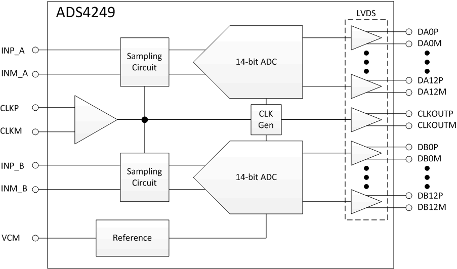
ADS4249 框图

ADS4249 frontpage1_bas534.gif

4 修订历史记录

Changes from D Revision (May 2015) to E Revision

  • Changed Pin Functions (LVDS Mode) table to comply with RGC Package (LVDS Mode) pin out diagramGo
  • Changed Pin Functions (CMOS Mode) table to comply with RGC Package (CMOS Mode) pin out diagram Go
  • Changed unit in last row of Clock Input, Input clock amplitude differential parameter to VPP in Recommended Operating Conditions tableGo
  • Added text reference for Table 5 Go

Changes from C Revision (July 2012) to D Revision

  • Added 引脚配置和功能部分,ESD 额定值表,特性 描述 部分,器件功能模式,应用和实施部分,电源相关建议部分,布局部分,器件和文档支持部分以及机械、封装和可订购信息部分Go

Changes from B Revision (September 2011) to C Revision

  • Changed footnote 1 in CMOS Timings at Lower Sampling FrequenciesGo
  • Changed conditions for ADS4249 Typical Characteristics sectionGo
  • Changed register D5h bit names of bits D7, D4, D3, and D0 in Table 10Go
  • Changed register address D8 to DB in Table 10Go
  • Changed register address D5h to match change in Table 10Go
  • Changed register address DB to match change in Table 10Go

Changes from A Revision (September 2011) to B Revision

  • Changed 文档状态至“量产数据”Go
  • Changed AC power-supply rejection ratio parameter test condition in ADS4249 Electrical Characteristics tableGo

5 ADS424x, ADS422x Family Comparison(1)

65 MSPS 125 MSPS 160 MSPS 250 MSPS
ADS422x
12-bit family
ADS4222 ADS4225 ADS4226 ADS4229
ADS424x
14-bit family
ADS4242 ADS4245 ADS4246 ADS4249
(1) See Table 1 for details on migrating from the ADS62P49 family.

The ADS4249 is pin-compatible with the previous generation ADS62P49 data converter; this similar architecture enables easy migration. However, there are some important differences between the two device generations, summarized in Table 1.

Table 1. Migrating from the ADS62P49

ADS62P49 ADS4249
PINS
Pin 22 is NC (not connected) Pin 22 is AVDD
Pins 38 and 58 are DRVDD Pins 38 and 58 are NC (do not connect, must be floated)
Pins 39 and 59 are DRGND Pins 39 and 59 are NC (do not connect, must be floated)
SUPPLY
AVDD is 3.3 V AVDD is 1.8 V
DRVDD is 1.8 V No change
INPUT COMMON-MODE VOLTAGE
VCM is 1.5 V VCM is 0.95 V
SERIAL INTERFACE
Protocol: 8-bit register address and 8-bit register data No change in protocol
New serial register map
EXTERNAL REFERENCE
Supported Not supported

6 Pin Configuration and Functions

RGC Package (LVDS Mode)
64-Pin VQFN
Top View
ADS4249 po_lvds_bas534.gif

NOTE:

The PowerPAD is connected to DRGND.
NC = do not connect; must float.

Pin Functions (LVDS Mode)

PIN I/O DESCRIPTION
NAME NO.
AGND 17 I Analog ground
18
21
24
27
28
31
32
AVDD 16 I Analog power supply
22
33
34
CLKM 26 I Differential clock negative input
CLKP 25 I Differential clock positive input
CLKOUTP 57 O Differential output clock, true
CLKOUTM 56 O Differential output clock, complement
CTRL1 35 I Digital control input pins. Together, these pins control the various power-down modes.
CTRL2 36
CTRL3 37
DA0M 40 O Channel A differential output data pair, D0 and D1 multiplexed
DA0P 41
DA2M 42 O Channel A differential output data D2 and D3 multiplexed
DA2P 43
DA4M 44 O Channel A differential output data D4 and D5 multiplexed
DA4P 45
DA6M 46 O Channel A differential output data D6 and D7 multiplexed
DA6P 47
DA8M 50 O Channel A differential output data D8 and D9 multiplexed
DA8P 51
DA10M 52 O Channel A differential output data D10 and D11 multiplexed
DA10P 53
DA12M 54 O Channel A differential output data D12 and D13 multiplexed
DA12P 55
DB0M 60 O Channel B differential output data pair, D0 and D1 multiplexed
DB0P 61
DB2M 62 O Channel B differential output data D2 and D3 multiplexed
DB2P 63
DB4M 2 O Channel B differential output data D4 and D5 multiplexed
DB4P 3
DB6M 4 O Channel B differential output data D6 and D7 multiplexed
DB6P 5
DB8M 6 O Channel B differential output data D8 and D9 multiplexed
DB8P 7
DB10M 8 O Channel B differential output data D10 and D11 multiplexed
DB10P 9
DB12M 10 O Channel B differential output data D12 and D13 multiplexed
DB12P 11
DRGND 49 I Output buffer ground
PAD
DRVDD 1 I Output buffer supply
48
INM_A 30 I Differential analog negative input, channel A
INP_A 29 I Differential analog positive input, channel A
INM_B 20 I Differential analog negative input, channel B
INP_B 19 I Differential analog positive input, channel B
NC 38 — Do not connect, must be floated
39
58
59
RESET 12 I Serial interface RESET input.
When using the serial interface mode, the internal registers must be initialized through a hardware RESET by applying a high pulse on this pin or by using the software reset option; see the Serial Interface Configuration section.
In parallel interface mode, the RESET pin must be permanently tied high. SCLK and SEN are used as parallel control pins in this mode. This pin has an internal 150-kΩ pull-down resistor.
SCLK 13 I This pin functions as a serial interface clock input when RESET is low. SCLK controls the low-speed mode selection when RESET is tied high; see Table 7 for detailed information. This pin has an internal 150-kΩ pull-down resistor.
SDATA 14 I Serial interface data input; this pin has an internal 150-kΩ pull-down resistor.
SDOUT 64 O This pin functions as a serial interface register readout when the READOUT bit is enabled. When READOUT = 0, this pin is put into a high-impedance state.
SEN 15 I This pin functions as a serial interface enable input when RESET is low. SEN controls the output interface and data format selection when RESET is tied high; see Table 8 for detailed information. This pin has an internal 150-kΩ pull-up resistor to AVDD.
VCM 23 O This pin outputs the common-mode voltage (0.95 V) that can be used externally to bias the analog input pins
RGC Package (CMOS Mode)
64-Pin VQFN
Top View
ADS4249 po_cmos_bas534.gif

NOTE:

The PowerPAD is connected to DRGND.
NC = do not connect; must float.

Pin Functions (CMOS Mode)

PIN I/O DESCRIPTION
NAME NO.
AGND 17 I Analog ground
18
21
24
27
28
31
32
AVDD 16 I Analog power supply
22
33
34
CLKM 26 I Differential clock negative input
CLKP 25 I Differential clock positive input
CLKOUT 57 O CMOS output clock
CTRL1 35 I Digital control input pins. Together, these pins control various power-down modes.
CTRL2 36
CTRL3 37
DA0 40 O Channel A ADC output data bits, CMOS levels
DA1 41
DA2 42
DA3 43
DA4 44
DA5 45
DA6 46
DA7 47
DA8 50
DA9 51
DA10 52
DA11 53
DA12 54
DA13 55
DB0 60 O Channel B ADC output data bits, CMOS levels
DB1 61
DB2 62
DB3 63
DB4 2
DB5 3
DB6 4
DB7 5
DB8 6
DB9 7
DB10 8
DB11 9
DB12 10
DB13 11
DRGND 49 I Output buffer ground
PAD
DRVDD 1 I Output buffer supply
48
INM_A 30 I Differential analog negative input, channel A
INP_A 29 I Differential analog positive input, channel A
INM_B 20 I Differential analog negative input, channel B
INP_B 19 I Differential analog positive input, channel B
NC 38 — Do not connect, must be floated
39
58
59
RESET 12 I Serial interface RESET input.
When using the serial interface mode, the internal registers must be initialized through a hardware RESET by applying a high pulse on this pin or by using the software reset option; see the Serial Interface Configuration section.
In parallel interface mode, the RESET pin must be permanently tied high. SDATA and SEN are used as parallel control pins in this mode. This pin has an internal 150-kΩ pull-down resistor.
SCLK 13 I This pin functions as a serial interface clock input when RESET is low. SCLK controls the low-speed mode when RESET is tied high; see Table 7 for detailed information. This pin has an internal 150-kΩ pull-down resistor.
SDATA 14 I Serial interface data input; this pin has an internal 150-kΩ pull-down resistor.
SDOUT 64 O This pin functions as a serial interface register readout when the READOUT bit is enabled. When READOUT = 0, this pin is put into a high-impedance state.
SEN 15 I This pin functions as a serial interface enable input when RESET is low. SEN controls the output interface and data format selection when RESET is tied high; see Table 8 for detailed information. This pin has an internal 150-kΩ pull-up resistor to AVDD.
UNUSED 56 — This pin is not used in the CMOS interface
VCM 23 O This pin outputs the common-mode voltage (0.95 V) that can be used externally to bias the analog input pins

7 Specifications

7.1 Absolute Maximum Ratings(1)

MIN MAX UNIT
Supply voltage, AVDD –0.3 2.1 V
Supply voltage, DRVDD –0.3 2.1 V
Voltage between AGND and DRGND –0.3 0.3 V
Voltage between AVDD to DRVDD (when AVDD leads DRVDD) –2.4 2.4 V
Voltage between DRVDD to AVDD (when DRVDD leads AVDD) –2.4 2.4 V
Voltage applied to input pins INP_A, INM_A, INP_B, INM_B –0.3 Minimum
(1.9, AVDD + 0.3)
V
CLKP, CLKM(2) –0.3 AVDD + 0.3
RESET, SCLK, SDATA, SEN,
CTRL1, CTRL2, CTRL3
–0.3 3.9
Operating free-air temperature, TA –40 85 °C
Operating junction temperature, TJ 125 °C
Storage temperature, Tstg –65 150 °C
(1) Stresses beyond those listed under Absolute Maximum Ratings may cause permanent damage to the device. These are stress ratings only, which do not imply functional operation of the device at these or any other conditions beyond those indicated under Recommended Operating Conditions. Exposure to absolute-maximum-rated conditions for extended periods may affect device reliability.
(2) When AVDD is turned off, switching off the input clock (or ensuring the voltage on CLKP, CLKM is less than |0.3 V|) is recommended. This configuration prevents the ESD protection diodes at the clock input pins from turning on.

7.2 ESD Ratings

VALUE UNIT
V(ESD) Electrostatic discharge Human body model (HBM), per ANSI/ESDA/JEDEC JS-001(1) ±2000 V
(1) JEDEC document JEP155 states that 500-V HBM allows safe manufacturing with a standard ESD control process.

7.3 Recommended Operating Conditions

Over operating free-air temperature range, unless otherwise noted.
MIN NOM MAX UNIT
SUPPLIES
Analog supply voltage, AVDD 1.7 1.8 1.9 V
Digital supply voltage, DRVDD 1.7 1.8 1.9 V
ANALOG INPUTS
Differential input voltage 2 VPP
Input common-mode VCM ± 0.05 V
Maximum analog input frequency with 2-VPP input amplitude(1) 400 MHz
Maximum analog input frequency with 1-VPP input amplitude(1) 600 MHz
CLOCK INPUT
Input clock sample rate Low-speed mode enabled(2) 1 80 MSPS
Low-speed mode disabled(2) (by default after reset) 80 250
Input clock amplitude differential
(VCLKP – VCLKM)
Sine wave, ac-coupled 0.2 1.5 VPP
LVPECL, ac-coupled 1.6
LVDS, ac-coupled 0.7
LVCMOS, single-ended, ac-coupled 1.5
Input clock duty cycle Low-speed mode disabled 35% 50% 65%
Low-speed mode enabled 40% 50% 60%
DIGITAL OUTPUTS
Maximum external load capacitance from each output pin to DRGND, CLOAD 5 pF
Differential load resistance between the LVDS output pairs (LVDS mode), RLOAD 100 Ω
Operating free-air temperature, TA –40 +85 °C
(1) See the Theory of Operation section.
(2) See the Serial Interface Configuration section for details on programming the low-speed mode.

7.4 Thermal Information

THERMAL METRIC(1) ADS4249 UNIT
RGC (VQFN)
64 PINS
RθJA Junction-to-ambient thermal resistance 23.9 °C/W
RθJC(top) Junction-to-case (top) thermal resistance 10.9 °C/W
RθJB Junction-to-board thermal resistance 4.3 °C/W
ψJT Junction-to-top characterization parameter 0.1 °C/W
ψJB Junction-to-board characterization parameter 4.4 °C/W
RθJC(bot) Junction-to-case (bottom) thermal resistance 0.6 °C/W
(1) For more information about traditional and new thermal metrics, see the Semiconductor and IC Package Thermal Metrics application report, SPRA953.

7.5 Electrical Characteristics: ADS4249 (250 MSPS)

Typical values are at +25°C, AVDD = 1.8 V, DRVDD = 1.8 V, 50% clock duty cycle, –1 dBFS differential analog input, LVDS interface, and 0-dB gain, unless otherwise noted. Minimum and maximum values are across the full temperature range:
TMIN = –40°C to TMAX = +85°C, AVDD = 1.8 V, and DRVDD = 1.8 V.
PARAMETER TEST CONDITIONS MIN TYP MAX UNIT
Resolution 14 Bits
SNR Signal-to-noise ratio fIN = 20 MHz 72.8 dBFS
fIN = 70 MHz 72.5
fIN = 100 MHz 72.2
fIN = 170 MHz 67.5 71.7
fIN = 300 MHz 69.4
SINAD Signal-to-noise and
distortion ratio
fIN = 20 MHz 72 dBFS
fIN = 70 MHz 71.6
fIN = 100 MHz 71.6
fIN = 170 MHz 66.5 70.7
fIN = 300 MHz 68.7
SFDR Spurious-free dynamic range fIN = 20 MHz 80 dBc
fIN = 70 MHz 79
fIN = 100 MHz 82
fIN = 170 MHz 71 80
fIN = 300 MHz 76
THD Total harmonic distortion fIN = 20 MHz 78 dBc
fIN = 70 MHz 77
fIN = 100 MHz 79
fIN = 170 MHz 69 76
fIN = 300 MHz 75
HD2 Second-order harmonic distortion fIN = 20 MHz 80 dBc
fIN = 70 MHz 79
fIN = 100 MHz 81
fIN = 170 MHz 71 80
fIN = 300 MHz 76
HD3 Third-order harmonic distortion fIN = 20 MHz 85 dBc
fIN = 70 MHz 87
fIN = 100 MHz 96
fIN = 170 MHz 71 80
fIN = 300 MHz 84
Worst spur
(other than second and third harmonics)
fIN = 20 MHz 92 dBc
fIN = 70 MHz 95
fIN = 100 MHz 94
fIN = 170 MHz 77 88
fIN = 300 MHz 85
IMD Two-tone intermodulation distortion f1 = 46 MHz, f2 = 50 MHz,
each tone at –7 dBFS
95 dBFS
f1 = 185 MHz, f2 = 190 MHz,
each tone at –7 dBFS
82
Crosstalk 20-MHz full-scale signal on channel under observation; 170-MHz full-scale signal on other channel 95 dB
Input overload recovery Recovery to within 1%
(of full-scale) for 6 dB overload with sine-wave input
1 Clock cycle
PSRR AC power-supply rejection ratio For 50-mVPP signal on AVDD supply, up to 10 MHz 30 dB
ENOB Effective number of bits fIN = 170 MHz 11.45 LSBs
DNL Differential nonlinearity fIN = 170 MHz –0.95 ±0.5 1.7 LSBs
INL Integrated nonlinearity fIN = 170 MHz ±2 ±4.5 LSBs

7.6 Electrical Characteristics: General

Typical values are at +25°C, AVDD = 1.8 V, DRVDD = 1.8 V, 50% clock duty cycle, and –1 dBFS differential analog input, unless otherwise noted. Minimum and maximum values are across the full temperature range: TMIN = –40°C to TMAX = +85°C, AVDD = 1.8 V, and DRVDD = 1.8 V.
PARAMETER MIN TYP MAX UNIT
ANALOG INPUTS
Differential input voltage range 2 VPP
Differential input resistance (at 200 MHz) 0.75 kΩ
Differential input capacitance (at 200 MHz) 3.7 pF
Analog input bandwidth
(with 50-Ω source impedance, and 50-Ω termination)
550 MHz
Analog input common-mode current
(per input pin of each channel)
1.5 µA/MSPS
VCM Common-mode output voltage 0.95(2) V
VCM output current capability 4 mA
DC ACCURACY
Offset error –15 2.5 15 mV
Temperature coefficient of offset error 0.003 mV/°C
EGREF Gain error as a result of internal reference inaccuracy alone –2 2 %FS
EGCHAN Gain error of channel alone ±0.1 1 %FS
Temperature coefficient of EGCHAN 0.002 Δ%/°C
POWER SUPPLY
IAVDD Analog supply current 167 190 mA
IDRVDD Output buffer supply current, LVDS interface, 350-mV swing with 100-Ω external termination, fIN = 2.5 MHz 144 160 mA
IDRVDD Output buffer supply current, CMOS interface, no load capacitance, fIN = 2.5 MHz(1) 94 mA
Analog power 301 342 mW
Digital power, LVDS interface, 350-mV swing with 100-Ω external termination, fIN = 2.5 MHz 259 288 mW
Digital power, CMOS interface, 8-pF external load capacitance(1),
fIN = 2.5 MHz
169 mW
Global power-down 25 mW
(1) In CMOS mode, the DRVDD current scales with the sampling frequency, the load capacitance on output pins, input frequency, and the supply voltage (see the CMOS Interface Power Dissipation section).
(2) VCM changes to 0.87 V when serial register bits HIGH PERF MODE[7:2] are set.

7.7 Digital Characteristics

At AVDD = 1.8 V and DRVDD = 1.8 V, unless otherwise noted. DC specifications refer to the condition where the digital outputs do not switch, but are permanently at a valid logic level 0 or 1.
PARAMETER TEST CONDITIONS MIN TYP MAX UNIT
DIGITAL INPUTS (RESET, SCLK, SDATA, SEN, CTRL1, CTRL2, CTRL3)(1)
High-level input voltage All digital inputs support 1.8-V and 3.3-V CMOS logic levels 1.3 V
Low-level input voltage 0.4 V
High-level input current SDATA, SCLK(2) VHIGH = 1.8 V 10 µA
SEN(3) VHIGH = 1.8 V 0
Low-level input current SDATA, SCLK VLOW = 0 V 0 µA
SEN VLOW = 0 V 10
DIGITAL OUTPUTS, CMOS INTERFACE (DA[13:0], DB[13:0], CLKOUT, SDOUT)
High-level output voltage DRVDD – 0.1 DRVDD V
Low-level output voltage 0 0.1 V
DIGITAL OUTPUTS, LVDS INTERFACE
High-level output
differential voltage
VODH With an external
100-Ω termination
270 350 430 mV
Low-level output
differential voltage
VODL With an external
100-Ω termination
–430 –350 –270 mV
Output common-mode voltage VOCM 0.9 1.05 1.25 V
(1) SCLK, SDATA, and SEN function as digital input pins in serial configuration mode.
(2) SDATA, SCLK have internal 150-kΩ pull-down resistor.
(3) SEN has an internal 150-kΩ pull-up resistor to AVDD. Because the pull-up is weak, SEN can also be driven by 1.8 V or 3.3 V CMOS buffers.

7.8 LVDS and CMOS Modes Timing Requirements

Typical values are at +25°C, AVDD = 1.8 V, DRVDD = 1.8 V, sampling frequency = 250 MSPS, sine wave input clock, CLOAD = 5 pF, and RLOAD = 100 Ω, unless otherwise noted. Minimum and maximum values are across the full temperature range: TMIN = –40°C to TMAX = +85°C, AVDD = 1.8 V, and DRVDD = 1.7 V to 1.9 V.(1)
MIN TYP MAX UNIT
GENERAL
tA Aperture delay 0.5 0.8 1.1 ns
Aperture delay matching between the two channels of the same device ±70 ps
Variation of aperture delay between two devices at the same temperature and DRVDD supply ±150 ps
tJ Aperture jitter 140 fS rms
Wakeup time Time to valid data after coming out of STANDBY mode 50 100 µs
Time to valid data after coming out of GLOBAL power-down mode 100 500
ADC latency(4) Default latency after reset 16 Clock cycles
Digital functions enabled (EN DIGITAL = 1) 24
DDR LVDS MODE(2)
tSU Data setup time: data valid(3) to zero-crossing of CLKOUTP 0.6 0.88 ns
tH Data hold time: zero-crossing of CLKOUTP to data becoming invalid(3) 0.33 0.55 ns
tPDI Clock propagation delay: input clock rising edge cross-over to output clock rising edge cross-over 5 6 7.5 ns
LVDS bit clock duty cycle of differential clock, (CLKOUTP-CLKOUTM) 48%
tRISE,
tFALL
Data rise time, data fall time: rise time measured from –100 mV to +100 mV,
fall time measured from +100 mV to –100 mV,
1 MSPS ≤ sampling frequency ≤ 250 MSPS
0.13 ns
tCLKRISE,
tCLKFALL
Output clock rise time, output clock fall time: rise time measured from –100 mV to +100 mV, fall time measured from +100 mV to –100 mV, 1 MSPS ≤ sampling frequency ≤ 250 MSPS 0.13 ns
PARALLEL CMOS MODE
tPDI Clock propagation delay: input clock rising edge cross-over to output clock rising edge cross-over 4.5 6.2 8.5 ns
Output clock duty cycle of output clock (CLKOUT),
1 MSPS ≤ sampling frequency ≤ 200 MSPS
50%
tRISE,
tFALL
Data rise time, data fall time: rise time measured from 20% to 80% of DRVDD,
fall time measured from 80% to 20% of DRVDD,
1 MSPS ≤ sampling frequency ≤ 200 MSPS
0.7 ns
tCLKRISE,
tCLKFALL
Output clock rise time output clock fall time: rise time measured from 20% to 80% of DRVDD, fall time measured from 80% to 20% of DRVDD, 1 MSPS ≤ sampling frequency ≤ 200 MSPS 0.7 ns
(1) Timing parameters are ensured by design and characterization and not tested in production.
(2) Measurements are done with a transmission line of 100-Ω characteristic impedance between the device and the load. Setup and hold time specifications take into account the effect of jitter on the output data and clock.
(3) Data valid refers to a logic high of +100 mV and a logic low of –100 mV.
(4) At higher frequencies, tPDI is greater than one clock period and overall latency = ADC latency + 1.

7.9 LVDS Timings at Lower Sampling Frequencies

Typical values are at +25°C, AVDD = 1.8 V, DRVDD = 1.8 V, sampling frequency = 250 MSPS, sine wave input clock, CLOAD = 5 pF, and RLOAD = 100 Ω, unless otherwise noted. Minimum and maximum values are across the full temperature range: TMIN = –40°C to TMAX = +85°C, AVDD = 1.8 V, and DRVDD = 1.7 V to 1.9 V.
SAMPLING FREQUENCY (MSPS) SETUP TIME (ns) HOLD TIME (ns) tPDI, CLOCK PROPAGATION
DELAY (ns)
MIN TYP MAX MIN TYP MAX MIN TYP MAX
65 5.9 6.6 0.35 0.6 5 6 7.5
80 4.5 5.2 0.35 0.6 5 6 7.5
125 2.3 2.9 0.35 0.6 5 6 7.5
160 1.5 2 0.33 0.55 5 6 7.5
185 1.3 1.6 0.33 0.55 5 6 7.5
200 1.1 1.4 0.33 0.55 5 6 7.5
230 0.76 1.06 0.33 0.55 5 6 7.5

7.10 CMOS Timings at Lower Sampling Frequencies

Typical values are at +25°C, AVDD = 1.8 V, DRVDD = 1.8 V, sampling frequency = 250 MSPS, sine wave input clock, CLOAD = 5 pF, and RLOAD = 100 Ω, unless otherwise noted. Minimum and maximum values are across the full temperature range: TMIN = –40°C to TMAX = +85°C, AVDD = 1.8 V, and DRVDD = 1.7 V to 1.9 V.
SAMPLING FREQUENCY (MSPS) TIMINGS SPECIFIED WITH RESPECT TO CLKOUT
SETUP TIME(1) (ns) HOLD TIME(1) (ns) tPDI, CLOCK PROPAGATION
DELAY (ns)
MIN TYP MAX MIN TYP MAX MIN TYP MAX
65 6.1 6.7 6.7 7.5 4.5 6.2 8.5
80 4.7 5.2 5.3 6 4.5 6.2 8.5
125 2.7 3.1 3.1 3.6 4.5 6.2 8.5
160 1.6 2.1 2.3 2.8 4.5 6.2 8.5
185 1.1 1.6 1.9 2.4 4.5 6.2 8.5
200 1 1.4 1.7 2.2 4.5 6.2 8.5
(1) In CMOS mode, setup time is measured from the beginning of data valid to 50% of the CLKOUT rising edge, whereas hold time is measured from 50% of the CLKOUT rising edge to data becoming invalid. Data valid refers to a logic high of 1.26 V and a logic low of 0.54 V.

7.11 Serial Interface Timing Characteristics

Typical values at +25°C; minimum and maximum values across the full temperature range: TMIN = –40°C to TMAX = +85°C,
AVDD = 1.8 V, and DRVDD = 1.8 V, unless otherwise noted.
MIN TYP MAX UNIT
fSCLK SCLK frequency (equal to 1 / tSCLK) > dc 20 MHz
tSLOADS SEN to SCLK setup time 25 ns
tSLOADH SCLK to SEN hold time 25 ns
tDSU SDATA setup time 25 ns
tDH SDATA hold time 25 ns

7.12 Reset Timing (Only when Serial Interface is Used)

Typical values at +25°C; minimum and maximum values across the full temperature range: TMIN = –40°C to TMAX = +85°C, unless otherwise noted.
MIN TYP MAX UNIT
t1 Power-on delay from AVDD and DRVDD power-up to active RESET pulse 1 ms
t2 Reset pulse duration; active RESET signal pulse duration 10 ns
1 µs
t3 Register write delay from RESET disable to SEN active 100 ns
ADS4249 tim_lvds_vo_level_bas550.gif
1. With external 100-Ω termination.
Figure 1. LVDS Output Voltage Levels
ADS4249 tim_cmos_iface_bas533.gif
1. Dn = bits D0, D1, D2, and so forth, of channels A and B.
Figure 2. CMOS Interface Timing Diagram
ADS4249 tim_latency_bas534.gif
1. ADC latency after reset. At higher sampling frequencies, tPDI is greater than one clock cycle, which then makes the overall latency = ADC latency + 1.
2. E = even bits (D0, D2, D4, and so forth); O = odd bits (D1, D3, D5, and so forth).
Figure 3. Latency Timing Diagram
ADS4249 tim_lvds_iface_bas534.gif Figure 4. LVDS Interface Timing Diagram
ADS4249 tim_serial_iface_bas534.gif Figure 5. Serial Interface Timing
ADS4249 tim_reset_bas533.gif

NOTE:

A high pulse on the RESET pin is required in the serial interface mode when initialized through a hardware reset. For parallel interface operation, RESET must be permanently tied high.
Figure 6. Reset Timing Diagram

7.13 Typical Characteristics

7.13.1 Typical Characteristics: ADS4249

At TA = +25°C, AVDD = 1.8 V, DRVDD = 1.8 V, maximum rated sampling frequency, sine wave input clock, 1.5 VPP differential clock amplitude, 50% clock duty cycle, –1-dBFS differential analog input, High-Performance Mode enabled, 0-dB gain, DDR LVDS output interface, and 32k point FFT, unless otherwise noted.
ADS4249 tc_fft_10mhz_bas534.png Figure 7. Input Signal (10 MHz)
ADS4249 tc_fft_300mhz_bas534.png Figure 9. Input Signal (300 MHz)
ADS4249 tc_fft_2tone_ver2_bas534.png Figure 11. Two-Tone Input Signal
ADS4249 tc_snr-fin_bas534.png Figure 13. SNR vs Input Frequency
ADS4249 tc_sinad-g_fin_bas534.png Figure 15. SINAD vs Gain and Input Frequency
ADS4249 tc_perf-inamp_ver2_bas534.png Figure 17. Performance vs Input Amplitude
ADS4249 tc_perf-in_vcm_ver2_bas534.png Figure 19. Performance vs Input Common-Mode Voltage
ADS4249 tc_snr-tmp_avdd_bas534.png Figure 21. SNR vs Temperature and AVDD Supply
ADS4249 tc_perf-in_clk_amp_ver1_bas534.png Figure 23. Performance vs Input Clock Amplitude
ADS4249 tc_perf-in_clk_dcy_bas534.png Figure 25. Performance vs Input Clock Duty Cycle
ADS4249 tc_cmrr_bas534.gif Figure 27. CMRR Spectrum
ADS4249 tc_psrr_bas534.gif Figure 29. Zoomed View of PSRR Spectrum
ADS4249 tc_digi_pwr_bas534.png Figure 31. Digital Power LVDS CMOS
ADS4249 tc_fft_150mhz_bas534.png Figure 8. Input Signal (150 MHz)
ADS4249 tc_fft_2tone_ver1_bas534.png Figure 10. Two-Tone Input Signal
ADS4249 tc_sfdr-fin_bas534.png Figure 12. SFDR vs Input Frequency
ADS4249 tc_sfdr-g_fin_bas534.png Figure 14. SFDR vs Gain and Input Frequency
ADS4249 tc_perf-inamp_ver1_bas534.png Figure 16. Performance vs Input Amplitude
ADS4249 tc_perf-in_vcm_ver1_bas534.png Figure 18. Performance vs Input Common-Mode Voltage
ADS4249 tc_sfdr-tmp_avdd_bas534.png Figure 20. SFDR vs Temperature and AVDD Supply
ADS4249 tc_perf-drvdd_bas534.png Figure 22. Performance vs DRVDD Supply Voltage
ADS4249 tc_perf-in_clk_amp_ver2_bas534.png Figure 24. Performance vs Input Clock Amplitude
ADS4249 tc_cmrr-test_bas534.png Figure 26. CMRR vs Test Signal Frequency
ADS4249 tc_psrr-test_bas534.png Figure 28. PSRR vs Test Signal Frequency
ADS4249 tc_ana_pwr-fsample_bas534.png Figure 30. Analog Power vs Sampling Frequency
ADS4249 tc_digi_pwr_various_bas534.png Figure 32. Digital Power in Various Modes

7.13.2 Typical Characteristics: Contour

All graphs are at +25°C, AVDD = 1.8 V, DRVDD = 1.8 V, maximum rated sampling frequency, sine wave input clock. 1.5 VPP differential clock amplitude, 50% clock duty cycle, –1-dBFS differential analog input, High-Performance Mode disabled, 0-dB gain, DDR LVDS output interface, and 32k point FFT, unless otherwise noted.
ADS4249 tc_contour_sfdr_0db_bas534.gif Figure 33. Spurious-Free Dynamic Range (0-dB Gain)
ADS4249 tc_contour_sfdr_6db_bas534.gif Figure 34. Spurious-Free Dynamic Range (6-dB Gain)
ADS4249 tc_contour_snr_0db_bas534.gif Figure 35. Signal-to-Noise Ratio (0-dB Gain)
ADS4249 tc_contour_snr_6db_bas534.gif Figure 36. Signal-to-Noise Ratio (6-dB Gain)

8 Detailed Description

8.1 Overview

The ADS4249 belongs to TI's ultralow power family of dual-channel, 14-bit analog-to-digital converters (ADCs). High performance is maintained when reducing power for power sensitive applications. In addition to its low power and high performance, the ADS4249 has a number of digital features and operating modes to enable design flexibility.

8.2 Functional Block Diagram

ADS4249 fbd_bas534.gif

8.3 Feature Description

8.3.1 Digital Functions

The device has several useful digital functions (such as test patterns, gain, and offset correction). These functions require extra clock cycles for operation and increase the overall latency and power of the device. These digital functions are disabled by default after reset and the raw ADC output is routed to the output data pins with a latency of 16 clock cycles. Figure 37 shows more details of the processing after the ADC. In order to use any of the digital functions, the EN DIGITAL bit must be set to '1'. After this, the respective register bits must be programmed as described in the following sections and in the Serial Register Map section.

ADS4249 ai_digi_processing_fbd_bas534.gif Figure 37. Digital Processing Block

8.3.2 Gain for SFDR, SNR Trade-Off

The ADS4249 includes gain settings that can be used to get improved SFDR performance (compared to no gain). The gain is programmable from 0 dB to 6 dB (in 0.5-dB steps). For each gain setting, the analog input full-scale range scales proportionally, as shown in Table 2.

The SFDR improvement is achieved at the expense of SNR; for each gain setting, the SNR degrades approximately between 0.5 dB and 1 dB. The SNR degradation is reduced at high input frequencies. As a result, the gain is very useful at high input frequencies because the SFDR improvement is significant with marginal degradation in SNR. Therefore, the gain can be used as a trade-off between SFDR and SNR. Note that the default gain after reset is 0 dB.

Table 2. Full-Scale Range Across Gains

GAIN (dB) TYPE FULL-SCALE (VPP)
0 Default after reset 2
1 Fine, programmable 1.78
2 Fine, programmable 1.59
3 Fine, programmable 1.42
4 Fine, programmable 1.26
5 Fine, programmable 1.12
6 Fine, programmable 1

8.3.3 Offset Correction

The ADS4249 has an internal offset correction algorithm that estimates and corrects dc offset up to ±10 mV. The correction can be enabled using the ENABLE OFFSET CORR serial register bit. When enabled, the algorithm estimates the channel offset and applies the correction every clock cycle. The time constant of the correction loop is a function of the sampling clock frequency. The time constant can be controlled using the OFFSET CORR TIME CONSTANT register bits, as described in Table 3.

After the offset is estimated, the correction can be frozen by setting FREEZE OFFSET CORR = 0. When frozen, the last estimated value is used for the offset correction of every clock cycle. Note that offset correction is disabled by default after reset.

Table 3. Time Constant of Offset Correction Algorithm

OFFSET CORR TIME CONSTANT TIME CONSTANT, TCCLK
(Number of Clock Cycles)
TIME CONSTANT, TCCLK × 1/fS (ms)(1)
0000 1 M 4
0001 2 M 8
0010 4 M 16
0011 8 M 32
0100 16 M 64
0101 32 M 128
0110 64 M 256
0111 128 M 512
1000 256 M 1024
1001 512 M 2048
1010 1 G 4096
1011 2 G 8192
1100 Reserved —
1101 Reserved —
1110 Reserved —
1111 Reserved —
(1) Sampling frequency, fS = 250 MSPS.

8.3.4 Power-Down

The ADS4249 has two power-down modes: global power-down and channel standby. These modes can be set using either the serial register bits or using the control pins CTRL1 to CTRL3 (as shown in Table 4).

Table 4. Power-Down Settings

CTRL1 CTRL2 CTRL3 DESCRIPTION
Low Low Low Default
Low Low High Not available
Low High Low Not available
Low High High Not available
High Low Low Global power-down
High Low High Channel A powered down, channel B is active
High High Low Not available
High High High MUX mode of operation, channel A and B data is multiplexed and output on DB[13:0] pins

8.3.4.1 Global Power-Down

In this mode, the entire chip (including ADCs, internal reference, and output buffers) are powered down, resulting in reduced total power dissipation of approximately 20 mW when the CTRL pins are used and 3mW when the PDN GLOBAL serial register bit is used. The output buffers are in high-impedance state. The wake-up time from global power-down to data becoming valid in normal mode is typically 100 µs.

8.3.4.2 Channel Standby

In this mode, each ADC channel can be powered down. The internal references are active, resulting in a quick wake-up time of 50 µs. The total power dissipation in standby is approximately 240 mW at 250 MSPS.

8.3.4.3 Input Clock Stop

In addition to the previous modes, the converter enters a low-power mode when the input clock frequency falls below 1 MSPS. The power dissipation is approximately 160 mW.

8.3.5 Output Data Format

Two output data formats are supported: twos complement and offset binary. The format can be selected using the DATA FORMAT serial interface register bit or by controlling the DFS pin in parallel configuration mode.

In the event of an input voltage overdrive, the digital outputs go to the appropriate full-scale level. For a positive overdrive, the output code is 3FFFh for the ADS4249 in offset binary output format; the output code is 1FFFh for the ADS4249 in twos complement output format. For a negative input overdrive, the output code is 0000h in offset binary output format and 2000h for the ADS4249 in twos complement output format.

8.4 Device Functional Modes

8.4.1 Output Interface Modes

The ADS4249 provides 14-bit digital data for each channel and an output clock synchronized with the data.

8.4.1.1 Output Interface

Two output interface options are available: double data rate (DDR) LVDS and parallel CMOS. They can be selected using the serial interface register bit or by setting the proper voltage on the SEN pin in parallel configuration mode.

8.4.1.2 DDR LVDS Outputs

In this mode, the data bits and clock are output using low-voltage differential signal (LVDS) levels. Two data bits are multiplexed and output on each LVDS differential pair, as shown in Figure 38.

ADS4249 ai_lvds_out_bas534.gif Figure 38. LVDS Interface

Even data bits (D0, D2, D4, and so forth) are output at the CLKOUTP rising edge and the odd data bits (D1, D3, D5, and so forth) are output at the CLKOUTP falling edge. Both the CLKOUTP rising and falling edges must be used to capture all the data bits, as shown in Figure 39.

ADS4249 tim_lvds_iface_bas534.gif Figure 39. DDR LVDS Interface Timing

8.4.1.3 LVDS Buffer

The equivalent circuit of each LVDS output buffer is shown in Figure 40. After reset, the buffer presents an output impedance of 100Ω to match with the external 100-Ω termination.

ADS4249 ai_lvds_buf_equiv_cir_bas550.gif

NOTE:

Default swing across 100-Ω load is ±350 mV. Use the LVDS SWING bits to change the swing.
Figure 40. LVDS Buffer Equivalent Circuit

The VDIFF voltage is nominally 350 mV, resulting in an output swing of ±350 mV with 100-Ω external termination. The VDIFF voltage is programmable using the LVDS SWING register bits from ±125 mV to ±570 mV.

Additionally, a mode exists to double the strength of the LVDS buffer to support 50-Ω differential termination, as shown in Figure 41. This mode can be used when the output LVDS signal is routed to two separate receiver chips, each using a 100-Ω termination. The mode can be enabled using the LVDS DATA STRENGTH and LVDS CLKOUT STRENGTH register bits for data and output clock buffers, respectively.

The buffer output impedance behaves in the same way as a source-side series termination. Absorbing reflections from the receiver end helps improve signal integrity.

ADS4249 ai_lvds_diff_termination_bas550.gif Figure 41. LVDS Buffer Differential Termination

8.4.1.4 Parallel CMOS Interface

In the CMOS mode, each data bit is output on separate pins as CMOS voltage level, every clock cycle, as Figure 42 shows. The rising edge of the output clock CLKOUT can be used to latch data in the receiver. Minimizing the load capacitance of the data and clock output pins is recommended by using short traces to the receiver. Furthermore, match the output data and clock traces to minimize the skew between them.

ADS4249 ai_cmos_out_bas534.gif Figure 42. CMOS Outputs

8.4.1.5 CMOS Interface Power Dissipation

With CMOS outputs, the DRVDD current scales with the sampling frequency and the load capacitance on every output pin. The maximum DRVDD current occurs when each output bit toggles between 0 and 1 every clock cycle. In actual applications, this condition is unlikely to occur. The actual DRVDD current would be determined by the average number of output bits switching, which is a function of the sampling frequency and the nature of the analog input signal. This relationship is shown by Equation 1:

Equation 1. Digital current as a result of CMOS output switching = CL × DRVDD × (N × FAVG)

where

  • CL = load capacitance,
  • N × FAVG = average number of output bits switching.

8.4.1.6 Multiplexed Mode of Operation

In this mode, the digital outputs of both channels are multiplexed and output on a single bus (DB[11:0] pins), as shown in Figure 43. The channel A output pins (DA[11:0]) are in 3-state. Because the output data rate on the DB bus is effectively doubled, this mode is recommended only for low sampling frequencies (less than 80 MSPS). This mode can be enabled using the POWER-DOWN MODE register bits or using the CTRL[3:1] parallel pins.

ADS4249 ai_tim_multiplex_mode_bas533.gif
1. In multiplexed mode, both channels outputs come on the channel B output pins.
2. Dn = bits D0, D1, D2, and so forth.
Figure 43. Multiplexed Mode Timing Diagram

8.5 Programming

The ADS4249 can be configured independently using either parallel interface control or serial interface programming. Table 5 lists the device high-performance modes.

Table 5. High-Performance Modes(1)(2)

PARAMETER DESCRIPTION
High-performance mode Set the HIGH PERF MODE[2:1] register bit to obtain best performance across sample clock and input signal frequencies.
Register address = 03h, data = 03h
High-frequency mode Set the HIGH FREQ MODE CH A and HIGH FREQ MODE CH B register bits for high input signal frequencies greater than 200 MHz.
Register address = 4Ah, data = 01h
Register address = 58h, data = 01h
High-speed mode Set the HIGH PERF MODE[8:3] bits to obtain best performance across input signal frequencies for sampling rates greater than 160 MSPS.
Note that this mode changes VCM to 0.87 V from its default value of 0.95 V.
Register address = 2h, data = 40h
Register address = D5h, data = 18h
Register address = D7h, data = 0Ch
Register address = DBh, data = 20h
(1) Using these modes to obtain best performance is recommended.
(2) See the Serial Interface Configuration section for details on register programming.

8.5.1 Parallel Configuration Only

To put the device into parallel configuration mode, keep RESET tied high (AVDD). Then, use the SEN, SCLK, CTRL1, CTRL2, and CTRL3 pins to directly control certain modes of the ADC. The device can be easily configured by connecting the parallel pins to the correct voltage levels (as described in Table 6 to Table 9). There is no need to apply a reset and SDATA can be connected to ground.

In this mode, SEN and SCLK function as parallel interface control pins. Some frequently-used functions can be controlled using these pins. Table 6 describes the modes controlled by the parallel pins.

Table 6. Parallel Pin Definition

PIN CONTROL MODE
SCLK Low-speed mode selection
SEN Output data format and output interface selection
CTRL1 Together, these pins control the power-down modes
CTRL2
CTRL3

8.5.2 Serial Interface Configuration Only

To enable this mode, the serial registers must first be reset to the default values and the RESET pin must be kept low. SEN, SDATA, and SCLK function as serial interface pins in this mode and can be used to access the internal registers of the ADC. The registers can be reset either by applying a pulse on the RESET pin or by setting the RESET bit high. The Serial Register Map section describes the register programming and the register reset process in more detail.

8.5.3 Using Both Serial Interface and Parallel Controls

For increased flexibility, a combination of serial interface registers and parallel pin controls (CTRL1 to CTRL3) can also be used to configure the device. To enable this option, keep RESET low. The parallel interface control pins CTRL1 to CTRL3 are available. After power-up, the device is automatically configured according to the voltage settings on these pins (see Table 9). SEN, SDATA, and SCLK function as serial interface digital pins and are used to access the internal registers of the ADC. The registers must first be reset to the default values either by applying a pulse on the RESET pin or by setting the RESET bit to '1'. After reset, the RESET pin must be kept low. The Serial Register Map section describes register programming and the register reset process in more detail.

8.5.4 Parallel Configuration Details

The functions controlled by each parallel pin are described in Table 7, Table 8, and Table 9. A simple way of configuring the parallel pins is shown in Figure 44.

Table 7. SCLK Control Pin

VOLTAGE APPLIED ON SCLK DESCRIPTION
Low Low-speed mode is disabled
High Low-speed mode is enabled

Table 8. SEN Control Pin

VOLTAGE APPLIED ON SEN DESCRIPTION
0
(50 mV / 0 mV)
Twos complement and parallel CMOS output
(3/8) AVDD
(±50 mV)
Offset binary and parallel CMOS output
(5/8) 2AVDD
(±5 0mV)
Offset binary and DDR LVDS output
AVDD
(0 mV / –50 mV)
Twos complement and DDR LVDS output

Table 9. CTRL1, CTRL2, and CTRL3 Pins

CTRL1 CTRL2 CTRL3 DESCRIPTION
Low Low Low Normal operation
Low Low High Not available
Low High Low Not available
Low High High Not available
High Low Low Global power-down
High Low High Channel A standby, channel B is active
High High Low Not available
High High High MUX mode of operation, channel A and B data are multiplexed and output on the DB[13:0] pins. See the Multiplexed Mode of Operation section for further details.
ADS4249 config_par_pins_bas533.gif Figure 44. Simple Scheme to Configure the Parallel Pins

8.5.5 Serial Interface Details

The ADC has a set of internal registers that can be accessed by the serial interface formed by the SEN (serial interface enable), SCLK (serial interface clock), and SDATA (serial interface data) pins. Serial shift of bits into the device is enabled when SEN is low. Serial data SDATA are latched at every SCLK falling edge when SEN is active (low). The serial data are loaded into the register at every 16th SCLK falling edge when SEN is low. When the word length exceeds a multiple of 16 bits, the excess bits are ignored. Data can be loaded in multiples of 16-bit words within a single active SEN pulse. The first eight bits form the register address and the remaining eight bits are the register data. The interface can work with SCLK frequencies from 20 MHz down to very low speeds (of a few hertz) and also with non-50% SCLK duty cycle.

8.5.5.1 Register Initialization

After power-up, the internal registers must be initialized to the default values. Initialization can be accomplished in one of two ways:

  1. Through a hardware reset by applying a high pulse on the RESET pin (of durations greater than 10 ns), see Figure 5 and the Serial Interface Timing Characteristics table; or
  2. By applying a software reset. When using the serial interface, set the RESET bit high. This setting initializes the internal registers to the default values and then self-resets the RESET bit low. In this case, the RESET pin is kept low. See the Reset Timing (Only when Serial Interface is Used) section and Figure 6 for reset timing.

8.5.5.2 Serial Register Readout

The device includes a mode where the contents of the internal registers can be read back. This readback mode may be useful as a diagnostic check to verify the serial interface communication between the external controller and the ADC. To use readback mode, follow this procedure:

  1. Set the READOUT register bit to '1'. This setting disables any further writes to the registers.
  2. Initiate a serial interface cycle specifying the address of the register (A7 to A0) whose content has to be read.
  3. The device outputs the contents (D7 to D0) of the selected register on the SDOUT pin (pin 64).
  4. The external controller can latch the contents at the SCLK falling edge.
  5. To enable register writes, reset the READOUT register bit to '0'.

The serial register readout works with both CMOS and LVDS interfaces on pin 64. Figure 45 shows the serial readout timing diagram.

When READOUT is disabled, the SDOUT pin is in high-impedance state.

ADS4249 tim_serial_readout_bas550.gif Figure 45. Serial Readout Timing Diagram

8.6 Register Maps

8.6.1 Serial Register Map

Table 10 summarizes the functions supported by the serial interface.

Table 10. Serial Interface Register Map(1)

REGISTER ADDRESS REGISTER DATA
A[7:0] (Hex) D7 D6 D5 D4 D3 D2 D1 D0
00 0 0 0 0 0 0 RESET READOUT
01 LVDS SWING 0 0
03 0 0 0 0 0 0 HIGH PERF MODE 2 HIGH PERF MODE 1
25 CH A GAIN 0 CH A TEST PATTERNS
29 0 0 0 DATA FORMAT 0 0 0
2B CH B GAIN 0 CH B TEST PATTERNS
3D 0 0 ENABLE OFFSET CORR 0 0 0 0 0
3F 0 0 CUSTOM PATTERN D[13:8]
40 CUSTOM PATTERN D[7:0]
41 LVDS CMOS CMOS CLKOUT STRENGTH 0 0 DIS OBUF
42 CLKOUT FALL POSN CLKOUT RISE POSN EN DIGITAL 0 0 0
45 STBY LVDS CLKOUT STRENGTH LVDS DATA STRENGTH 0 0 PDN GLOBAL 0 0
4A 0 0 0 0 0 0 0 HIGH FREQ MODE CH B
58 0 0 0 0 0 0 0 HIGH FREQ MODE CH A
BF CH A OFFSET PEDESTAL 0 0
C1 CH B OFFSET PEDESTAL 0 0
CF FREEZE OFFSET CORR 0 OFFSET CORR TIME CONSTANT 0 0
EF 0 0 0 EN LOW SPEED MODE 0 0 0 0
F1 0 0 0 0 0 0 EN LVDS SWING
F2 0 0 0 0 LOW SPEED MODE CH A 0 0 0
2 0 HIGH PERF MODE3 0 0 0 0 0 0
D5 0 0 0 HIGH PERF MODE4 HIGH PERF MODE5 0 0 0
D7 0 0 0 0 HIGH PERF MODE6 HIGH PERF MODE7 0 0
DB 0 0 HIGH PERF MODE8 0 0 0 0 LOW SPEED MODE CH B
(1) Multiple functions in a register can be programmed in a single write operation. All registers default to '0' after reset.

8.6.2 Description of Serial Registers

8.6.2.1 Register Address 00h (Default = 00h)

Figure 46. Register Address 00h (Default = 00h)
7 6 5 4 3 2 1 0
0 0 0 0 0 0 RESET READOUT
Bits[7:2] Always write '0'
Bit 1 RESET: Software reset applied
This bit resets all internal registers to the default values and self-clears to 0 (default = 1).
Bit 0 READOUT: Serial readout
This bit sets the serial readout of the registers.
0 = Serial readout of registers disabled; the SDOUT pin is placed in a high-impedance state.
1 = Serial readout enabled; the SDOUT pin functions as a serial data readout with CMOS logic levels running from the DRVDD supply. See the Serial Register Readout section.

8.6.2.2 Register Address 01h (Default = 00h)

Figure 47. Register Address 01h (Default = 00h)
7 6 5 4 3 2 1 0
LVDS SWING 0 0
Bits[7:2] LVDS SWING: LVDS swing programmability
These bits program the LVDS swing. Set the EN LVDS SWING bit to '1' before programming swing.
000000 = Default LVDS swing; ±350 mV with external 100-Ω termination
011011 = LVDS swing ±410 mV
110010 = LVDS swing ±465 mV
010100 = LVDS swing ±570 mV
111110 = LVDS swing ±200 mV
001111 = LVDS swing ±125 mV
Bits[1:0] Always write '0'

8.6.2.3 Register Address 01h (Default = 00h)

Figure 48. Register Address 03h (Default = 00h)
7 6 5 4 3 2 1 0
0 0 0 0 0 0 HIGH PERF MODE 2 HIGH PERF MODE 1
Bits[7:2] Always write '0'
Bits[1:0] HIGH PERF MODE[2:1]: High-performance mode
00 = Default performance
01 = Do not use
10 = Do not use
11 = Obtain best performance across sample clock and input signal frequencies

8.6.2.4 Register Address 25h (Default = 00h)

Figure 49. Register Address 25h (Default = 00h)
7 6 5 4 3 2 1 0
CH A GAIN 0 CH A TEST PATTERNS
Bits[7:4] CH A GAIN: Channel A gain programmability
These bits set the gain programmability in 0.5-dB steps for channel A.
0000 = 0-dB gain (default after reset)
0001 = 0.5-dB gain
0010 = 1-dB gain
0011 = 1.5-dB gain
0100 = 2-dB gain
0101 = 2.5-dB gain
0110 = 3-dB gain
0111 = 3.5-dB gain
1000 = 4-dB gain
1001 = 4.5-dB gain
1010 = 5-dB gain
1011 = 5.5-dB gain
1100 = 6-dB gain
Bit 3 Always write '0'
Bits[2:0] CH A TEST PATTERNS: Channel A data capture
These bits verify data capture for channel A.
000 = Normal operation
001 = Outputs all 0s
010 = Outputs all 1s
011 = Outputs toggle pattern.
The output data D[13:0] are an alternating sequence of 10101010101010 and 01010101010101.
100 = Outputs digital ramp.
101 = Outputs custom pattern; use registers 3Fh and 40h to set the custom pattern
110 = Unused
111 = Unused

8.6.2.5 Register Address 29h (Default = 00h)

Figure 50. Register Address 29h (Default = 00h)
7 6 5 4 3 2 1 0
0 0 0 DATA FORMAT 0 0 0
Bits[7:5] Always write '0'
Bits[4:3] DATA FORMAT: Data format selection
00 = Twos complement
01 = Twos complement
10 = Twos complement
11 = Offset binary
Bits[2:0] Always write '0'

8.6.2.6 Register Address 2Bh (Default = 00h)

Figure 51. Register Address 2Bh (Default = 00h)
7 6 5 4 3 2 1 0
CH B GAIN 0 CH B TEST PATTERNS
Bits[7:4] CH B GAIN: Channel B gain programmability
These bits set the gain programmability in 0.5-dB steps for channel B.
0000 = 0-dB gain (default after reset)
0001 = 0.5-dB gain
0010 = 1-dB gain
0011 = 1.5-dB gain
0100 = 2-dB gain
0101 = 2.5-dB gain
0110 = 3-dB gain
0111 = 3.5-dB gain
1000 = 4-dB gain
1001 = 4.5-dB gain
1010 = 5-dB gain
1011 = 5.5-dB gain
1100 = 6-dB gain
Bit 3 Always write '0'
Bits[2:0] CH B TEST PATTERNS: Channel B data capture
These bits verify data capture for channel B.
000 = Normal operation
001 = Outputs all 0s
010 = Outputs all 1s
011 = Outputs toggle pattern.
The output data D[13:0] are an alternating sequence of 10101010101010 and 01010101010101.
100 = Outputs digital ramp.
101 = Outputs custom pattern; use registers 3Fh and 40h to set the custom pattern
110 = Unused
111 = Unused

8.6.2.7 Register Address 3Dh (Default = 00h)

Figure 52. Register Address 3Dh (Default = 00h)
7 6 5 4 3 2 1 0
0 0 ENABLE OFFSET CORR 0 0 0 0 0
Bits[7:6] Always write '0'
Bit 5 ENABLE OFFSET CORR: Offset correction setting
This bit enables the offset correction.
0 = Offset correction disabled
1 = Offset correction enabled
Bits[4:0] Always write '0'

8.6.2.8 Register Address 3Fh (Default = 00h)

Figure 53. Register Address 3Fh (Default = 00h)
7 6 5 4 3 2 1 0
0 0 CUSTOM PATTERN D13 CUSTOM PATTERN D12 CUSTOM PATTERN D11 CUSTOM PATTERN D10 CUSTOM PATTERN D9 CUSTOM PATTERN D8
Bits[7:6] Always write '0'
Bits[5:0] CUSTOM PATTERN D[13:8]
These are the six upper bits of the custom pattern available at the output instead of ADC data.
The ADS4249 custom pattern is 14-bit.

8.6.2.9 Register Address 40h (Default = 00h)

Figure 54. Register Address 40h (Default = 00h)
7 6 5 4 3 2 1 0
CUSTOM PATTERN D7 CUSTOM PATTERN D6 CUSTOM PATTERN D5 CUSTOM PATTERN D4 CUSTOM PATTERN D3 CUSTOM PATTERN D2 CUSTOM PATTERN D1 CUSTOM PATTERN D0
Bits[7:0] CUSTOM PATTERN D[7:0]
These are the eight lower bits of the custom pattern available at the output instead of ADC data.
The ADS4249 custom pattern is 14-bit; use the CUSTOM PATTERN D[13:0] register bits.

8.6.2.10 Register Address 41h (Default = 00h)

Figure 55. Register Address 41h (Default = 00h)
7 6 5 4 3 2 1 0
LVDS CMOS CMOS CLKOUT STRENGTH 0 0 DIS OBUF
Bits[7:6] LVDS CMOS: Interface selection
These bits select the interface.
00 = DDR LVDS interface
01 = DDR LVDS interface
10 = DDR LVDS interface
11 = Parallel CMOS interface
Bits[5:4] CMOS CLKOUT STRENGTH
These bits control the strength of the CMOS output clock.
00 = Maximum strength (recommended)
01 = Medium strength
10 = Low strength
11 = Very low strength
Bits[3:2] Always write '0'
Bits[1:0] DIS OBUF
These bits power down data and clock output buffers for both the CMOS and LVDS output interface. When powered down, the output buffers are in 3-state.
00 = Default
01 = Power-down data output buffers for channel B
10 = Power-down data output buffers for channel A
11 = Power-down data output buffers for both channels as well as the clock output buffer

8.6.2.11 Register Address 42h (Default = 00h)

Figure 56. Register Address 42h (Default = 00h)
7 6 5 4 3 2 1 0
CLKOUT FALL POSN CLKOUT RISE POSN EN DIGITAL 0 0 0
Bits[7:6] CLKOUT FALL POSN
In LVDS mode:
00 = Default
01 = The falling edge of the output clock advances by 450 ps
10 = The falling edge of the output clock advances by 150 ps
11 = The falling edge of the output clock is delayed by 550 ps

In CMOS mode:
00 = Default
01 = The falling edge of the output clock is delayed by 150 ps
10 = Do not use
11 = The falling edge of the output clock advances by 100 ps
Bits[5:6] CLKOUT RISE POSN
In LVDS mode:
00 = Default
01 = The rising edge of the output clock advances by 450 ps
10 = The rising edge of the output clock advances by 150 ps
11 = The rising edge of the output clock is delayed by 250 ps

In CMOS mode:
00 = Default
01 = The rising edge of the output clock is delayed by 150 ps
10 = Do not use
11 = The rising edge of the output clock advances by 100 ps
Bit 3 EN DIGITAL: Digital function enable
0 = All digital functions disabled
1 = All digital functions (such as test patterns, gain, and offset correction) enabled
Bits[2:0] Always write '0'

8.6.2.12 Register Address 45h (Default = 00h)

Figure 57. Register Address 45h (Default = 00h)
7 6 5 4 3 2 1 0
STBY LVDS CLKOUT STRENGTH LVDS DATA STRENGTH 0 0 PDN GLOBAL 0 0
Bit 7 STBY: Standby setting
0 = Normal operation
1 = Both channels are put in standby; wakeup time from this mode is fast (typically 50 µs).
Bit 6 LVDS CLKOUT STRENGTH: LVDS output clock buffer strength setting
0 = LVDS output clock buffer at default strength to be used with 100-Ω external termination
1 = LVDS output clock buffer has double strength to be used with 50-Ω external termination
Bit 5 LVDS DATA STRENGTH
0 = All LVDS data buffers at default strength to be used with 100-Ω external termination
1 = All LVDS data buffers have double strength to be used with 50-Ω external termination
Bits[4:3] Always write '0'
Bit 2 PDN GLOBAL
0 = Normal operation
1 = Total power down; all ADC channels, internal references, and output buffers are powered down. Wakeup time from this mode is slow (typically 100 µs).
Bits[1:0] Always write '0'

8.6.2.13 Register Address 4Ah (Default = 00h)

Figure 58. Register Address 4Ah (Default = 00h)
7 6 5 4 3 2 1 0
0 0 0 0 0 0 0 HIGH FREQ MODE CH B
Bits[7:1] Always write '0'
Bit 0 HIGH FREQ MODE CH B: High-frequency mode for channel B
0 = Default
1 = Use this mode for high input frequencies greater than 200 MHz

8.6.2.14 Register Address 58h (Default = 00h)

Figure 59. Register Address 58h (Default = 00h)
7 6 5 4 3 2 1 0
0 0 0 0 0 0 0 HIGH FREQ MODE CH A
Bits[7:1] Always write '0'
Bit 0 HIGH FREQ MODE CH A: High-frequency mode for channel A
0 = Default
1 = Use this mode for high input frequencies greater than 200 MHz

8.6.2.15 Register Address BFh (Default = 00h)

Figure 60. Register Address BFh (Default = 00h)
7 6 5 4 3 2 1 0
CH A OFFSET PEDESTAL 0 0
Bits[7:4] CH A OFFSET PEDESTAL: Channel A offset pedestal selection
When the offset correction is enabled, the final converged value after the offset is corrected is the ADC midcode value. A pedestal can be added to the final converged value by programming these bits. See the Offset Correction section. Channels can be independently programmed for different offset pedestals by choosing the relevant register address.
The pedestal ranges from –32 to +31, so the output code can vary from midcode-32 to midcode+31 by adding pedestal D7-D2.
Program bits D[7:2]
011111 = Midcode+31
011110 = Midcode+30
011101 = Midcode+29
…
000010 = Midcode+2
000001 = Midcode+1
000000 = Midcode
111111 = Midcode-1
111110 = Midcode-2
…
100000 = Midcode-32
Bits[3:0] Always write '0'

8.6.2.16 Register Address C1h (Default = 00h)

Figure 61. Register Address C1h (Default = 00h)
7 6 5 4 3 2 1 0
CH B OFFSET PEDESTAL 0 0
Bits[7:4] CH B OFFSET PEDESTAL: Channel B offset pedestal selection
When offset correction is enabled, the final converged value after the offset is corrected is the ADC midcode value. A pedestal can be added to the final converged value by programming these bits; see the Offset Correction section. Channels can be independently programmed for different offset pedestals by choosing the relevant register address.
The pedestal ranges from –32 to +31, so the output code can vary from midcode-32 to midcode+31 by adding pedestal D7-D2.
Program Bits D[7:2]
011111 = Midcode+31
011110 = Midcode+30
011101 = Midcode+29
…
000010 = Midcode+2
000001 = Midcode+1
000000 = Midcode
111111 = Midcode-1
111110 = Midcode-2
…
100000 = Midcode-32
Bits[3:0] Always write '0'

8.6.2.17 Register Address CFh (Default = 00h)

Figure 62. Register Address CFh (Default = 00h)
7 6 5 4 3 2 1 0
FREEZE OFFSET CORR 0 OFFSET CORR TIME CONSTANT 0 0
Bit 7 FREEZE OFFSET CORR: Freeze offset correction setting
This bit sets the freeze offset correction estimation.
0 = Estimation of offset correction is not frozen (the EN OFFSET CORR bit must be set)
1 = Estimation of offset correction is frozen (the EN OFFSET CORR bit must be set); when frozen, the last estimated value is used for offset correction of every clock cycle. See the Offset Correction section.
Bit 6 Always write '0'
Bits[5:2] OFFSET CORR TIME CONSTANT
The offset correction loop time constant in number of clock cycles. See the Offset Correction section.
Bits[1:0] Always write '0'

8.6.2.18 Register Address EFh (Default = 00h)

Figure 63. Register Address EFh (Default = 00h)
7 6 5 4 3 2 1 0
0 0 0 EN LOW SPEED MODE 0 0 0 0
Bits[7:5] Always write '0'
Bit 4 EN LOW SPEED MODE: Enable control of low-speed mode through serial register bits
This bit enables the control of the low-speed mode using the LOW SPEED MODE CH B and LOW SPEED MODE CH A register bits.
0 = Low-speed mode is disabled
1 = Low-speed mode is controlled by serial register bits
Bits[3:0] Always write '0'

8.6.2.19 Register Address F1h (Default = 00h)

Figure 64. Register Address F1h (Default = 00h)
7 6 5 4 3 2 1 0
0 0 0 0 0 0 EN LVDS SWING
Bits[7:2] Always write '0'
Bits[1:0] EN LVDS SWING: LVDS swing enable
These bits enable LVDS swing control using the LVDS SWING register bits.
00 = LVDS swing control using the LVDS SWING register bits is disabled
01 = Do not use
10 = Do not use
11 = LVDS swing control using the LVDS SWING register bits is enabled

8.6.2.20 Register Address F2h (Default = 00h)

Figure 65. Register Address F2h (Default = 00h)
7 6 5 4 3 2 1 0
0 0 0 0 LOW SPEED MODE CH A 0 0 0
Bits[7:4] Always write '0'
Bit 3 LOW SPEED MODE CH A: Channel A low-speed mode enable
This bit enables the low-speed mode for channel A. Set the EN LOW SPEED MODE bit to '1' before using this bit.
0 = Low-speed mode is disabled for channel A
1 = Low-speed mode is enabled for channel A
Bits[2:0] Always write '0'

8.6.2.21 Register Address 2h (Default = 00h)

Figure 66. Register Address 2h (Default = 00h)
7 6 5 4 3 2 1 0
0 HIGH PERF MODE3 0 0 0 0 0 0
Bit 7 Always write '0'
Bit 6 HIGH PERF MODE3
HIGH PERF MODE3 to HIGH PERF MODE8 must be set to '1' to ensure best performance at high sampling speed (greater than 160 MSPS)
Bits[5:0] Always write '0'

8.6.2.22 Register Address D5h (Default = 00h)

Figure 67. Register Address D5h (Default = 00h)
7 6 5 4 3 2 1 0
0 0 0 HIGH PERF MODE4 HIGH PERF MODE5 0 0 0
Bits[7:5] Always write '0'
Bit 4 HIGH PERF MODE4
HIGH PERF MODE3 to HIGH PERF MODE8 must be set to '1' to ensure best performance at high sampling speed (greater than 160 MSPS)
Bit 3 HIGH PERF MODE5
HIGH PERF MODE3 to HIGH PERF MODE8 must be set to '1' to ensure best performance at high sampling speed (greater than 160 MSPS)
Bits[2:0] Always write '0'

8.6.2.23 Register Address D7h (Default = 00h)

Figure 68. Register Address D7h (Default = 00h)
7 6 5 4 3 2 1 0
0 0 0 0 HIGH PERF MODE6 HIGH PERF MODE7 0 0
Bits[7:4] Always write '0'
Bit 3 HIGH PERF MODE6
HIGH PERF MODE3 to HIGH PERF MODE8 must be set to '1' to ensure best performance at high sampling speed (greater than 160 MSPS)
Bit 2 HIGH PERF MODE7
HIGH PERF MODE3 to HIGH PERF MODE8 must be set to '1' to ensure best performance at high sampling speed (greater than 160 MSPS)
Bits[1:0] Always write '0'

8.6.2.24 Register Address DBh (Default = 00h)

Figure 69. Register Address DBh (Default = 00h)
7 6 5 4 3 2 1 0
0 0 HIGH PERF MODE8 0 0 0 0 LOW SPEED MODE CH B
Bits[7:6] Always write '0'
Bit 5 HIGH PERF MODE8
HIGH PERF MODE3 to HIGH PERF MODE8 must be set to '1' to ensure best performance at high sampling speed (greater than 160 MSPS).
Bits[4:1] Always write '0'
Bit 0 LOW SPEED MODE CH B: Channel B low-speed mode enable
This bit enables the low-speed mode for channel B. Set the EN LOW SPEED MODE bit to '1' before using this bit.
0 = Low-speed mode is disabled for channel B
1 = Low-speed mode is enabled for channel B

9 Application and Implementation

NOTE

Information in the following applications sections is not part of the TI component specification, and TI does not warrant its accuracy or completeness. TI’s customers are responsible for determining suitability of components for their purposes. Customers should validate and test their design implementation to confirm system functionality.

9.1 Application Information

The ADS4249 dual channel 14-bit ADC is designed for use in communications receivers designed to receive modern communication signals such as LTE, WIMAX, W-CDMA, and high-order QAM signals. A typical diversity receiver example is shown in Figure 70, where the antennas are placed at some distance to optimize performance in the presence of multipath fading. The path includes a low noise amplifier (LNA), RF mixer, and a digital variable gain amplifier (DVGA). Filtering is used throughout the path to remove blocking signals and mixing products and to prevent aliasing during sampling.

ADS4249 blockdiagram2_bas550.gif Figure 70. Diversity Communications Receiver

9.1.1 Theory of Operation

At every rising edge of the input clock, the analog input signal of each channel is simultaneously sampled. The sampled signal in each channel is converted by a pipeline of low-resolution stages. In each stage, the sampled/held signal is converted by a high-speed, low-resolution, flash sub-ADC. The difference between the stage input and the quantized equivalent is gained and propagates to the next stage. At every clock, each succeeding stage resolves the sampled input with greater accuracy. The digital outputs from all stages are combined in a digital correction logic block and digitally processed to create the final code after a data latency of 16 clock cycles. The digital output is available as either DDR LVDS or parallel CMOS and coded in either straight offset binary or binary twos complement format. The dynamic offset of the first stage sub-ADC limits the maximum analog input frequency to approximately 400 MHz (with 2-VPP amplitude) or approximately 600 MHz (with 1-VPP amplitude).

9.1.2 Analog Input

The analog input consists of a switched-capacitor-based, differential sample-and-hold (S/H) architecture. This differential topology results in very good ac performance even for high input frequencies at high sampling rates. The INP and INM pins must be externally biased around a common-mode voltage of 0.95 V, available on the VCM pin. For a full-scale differential input, each input pin (INP and INM) must swing symmetrically between
VCM + 0.5 V and VCM – 0.5 V, resulting in a 2-VPP differential input swing. The input sampling circuit has a high 3-dB bandwidth that extends up to 550 MHz (measured from the input pins to the sampled voltage). Figure 71 shows an equivalent circuit for the analog input.

ADS4249 ai_ana_in_cir_bas550.gif Figure 71. Analog Input Equivalent Circuit

9.1.2.1 Drive Circuit Requirements

For optimum performance, the analog inputs must be driven differentially. This operation improves the common-mode noise immunity and even-order harmonic rejection. A 5-Ω to 15-Ω resistor in series with each input pin is recommended to damp out ringing caused by package parasitics.

SFDR performance can be limited as a result of several reasons, including the effects of sampling glitches; nonlinearity of the sampling circuit; and nonlinearity of the quantizer that follows the sampling circuit. Depending on the input frequency, sample rate, and input amplitude, one of these factors generally plays a dominant part in limiting performance. At very high input frequencies (greater than approximately 300 MHz), SFDR is determined largely by the device sampling circuit nonlinearity. At low input amplitudes, the quantizer nonlinearity usually limits performance.

Glitches are caused by the opening and closing of the sampling switches. The driving circuit must present a low source impedance to absorb these glitches. Otherwise, glitches could limit performance, primarily at low input frequencies (up to approximately 200 MHz). Low impedance (less than 50 Ω) must be presented for the common-mode switching currents. This configuration can be achieved by using two resistors from each input terminated to the common-mode voltage (VCM pin).

The device includes an internal R-C filter from each input to ground. The purpose of this filter is to absorb the sampling glitches inside the device itself. The cutoff frequency of the R-C filter involves a trade-off. A lower cutoff frequency (larger C) absorbs glitches better but reduces the input bandwidth. On the other hand, with a higher cutoff frequency (smaller C), bandwidth support is maximized. However, the sampling glitches must then be supplied by the external drive circuit. This tradeoff has limitations as a result of the presence of the package bond-wire inductance.

In the ADS4249, the R-C component values have been optimized when supporting high input bandwidth (up to 550 MHz). However, in applications with input frequencies up to 200 MHz to 300 MHz, the filtering of the glitches can be improved further using an external R-C-R filter; see Figure 74 and Figure 75.

In addition, the drive circuit may have to be designed to provide a low insertion loss over the desired frequency range and matched impedance to the source. Furthermore, the ADC input impedance must be considered. Figure 72 and Figure 73 show the impedance (ZIN = RIN || CIN) looking into the ADC input pins.

ADS4249 ai_adc_rin-frq_bas533.gif Figure 72. ADC Analog Input Resistance (RIN) Across Frequency
ADS4249 ai_adc_cin-frq_bas533.gif Figure 73. ADC Analog Input Capacitance (CIN) Across Frequency

9.1.2.2 Driving Circuit

Three example driving circuit configurations are shown in Figure 74, Figure 75, and Figure 76. They are optimized for low bandwidth (low input frequencies), high bandwidth (higher input frequencies), and very high bandwidth (very high input frequencies), respectively. Note that three of the drive circuits have been terminated by 50 Ω near the ADC side. The termination is accomplished by a 25-Ω resistor from each input to the 0.95-V common-mode (VCM) from the device. This architecture allows the analog inputs to be biased around the required common-mode voltage.

The mismatch in the transformer parasitic capacitance (between the windings) results in degraded even-order harmonic performance. Connecting two identical RF transformers back-to-back helps minimize this mismatch; good performance is obtained for high-frequency input signals. For example, ADT1-1WT transformers can be used for the first two configurations (Figure 74 and Figure 75) ADTL2-18 transformers can be used for the third configuration (Figure 76). An optional termination resistor pair may be required between the two transformers, as shown in Figure 74, Figure 75, and Figure 76. The center point of this termination is connected to ground to improve the balance between the P and M sides. The values of the terminations between the transformers and on the secondary side must be chosen to obtain an effective 50 Ω (in the case of 50-Ω source impedance).

ADS4249 ai_drv_cir_lo_bas550.gif Figure 74. Drive Circuit with Low Bandwidth (for Low Input Frequencies Less Than 150 MHz)
ADS4249 ai_drv_cir_hi_bas550.gif Figure 75. Drive Circuit with High Bandwidth
(for High Input Frequencies Greater Than 150 MHz and Less Than 270 MHz)
ADS4249 ai_drv_cir_vhi_bas550.gif Figure 76. Drive Circuit with Very High Bandwidth (Greater than 270 MHz)

All of these examples show 1:1 transformers being used with a 50-Ω source. As explained in the Drive Circuit Requirements section, this configuration helps to present a low source impedance to absorb the sampling glitches. With a 1:4 transformer, the source impedance is 200 Ω. The higher source impedance is unable to absorb the sampling glitches effectively and can lead to degradation in performance (compared to using 1:1 transformers).

In almost all cases, either a band-pass or low-pass filter is required to obtain the desired dynamic performance, as shown in Figure 77. Such filters present low source impedance at the high frequencies corresponding to the sampling glitch and help avoid performance losses associated with the high source impedance.

ADS4249 ai_drv_cir_transformer_bas550.gif Figure 77. Drive Circuit with a 1:4 Transformer

9.1.3 Clock Input

The ADS4249 clock inputs can be driven differentially (sine, LVPECL, or LVDS) or single-ended (LVCMOS), with little or no difference in performance between them. The common-mode voltage of the clock inputs is set to VCM using internal 5-kΩ resistors. This setting allows the use of transformer-coupled drive circuits for sine-wave clock or ac-coupling for LVPECL and LVDS clock sources are illustrated in Figure 78, Figure 79, and Figure 80. The internal clock buffer is illustrated in Figure 81.

ADS4249 ai_dif_sinewave_clk_bas550.gif
1. RT = termination resister, if necessary.
Figure 78. Differential Sine-Wave Clock Driving Circuit
ADS4249 ai_lvds_clk_drv_bas550.gif Figure 79. LVDS Clock Driving Circuit
ADS4249 ai_lvpecl_clk_drv_bas550.gif Figure 80. LVPECL Clock Driving Circuit
ADS4249 ai_intclk_buffer_bas550.gif

NOTE:

CEQ is 1 pF to 3 pF and is the equivalent input capacitance of the clock buffer.
Figure 81. Internal Clock Buffer

A single-ended CMOS clock can be ac-coupled to the CLKP input, with CLKM connected to ground with a 0.1-μF capacitor, as shown in Figure 82. For best performance, the clock inputs must be driven differentially, thereby reducing susceptibility to common-mode noise. For high input frequency sampling, using a clock source with very low jitter is recommended. Band-pass filtering of the clock source can help reduce the effects of jitter. There is no change in performance with a non-50% duty cycle clock input.

ADS4249 ai_drv_cir_1end_bas550.gif Figure 82. Single-Ended Clock Driving Circuit

9.2 Typical Application

An example schematic for a typical application of the ADS4249 is shown in Figure 83.

ADS4249 typapp1.gif Figure 83. Example Schematic for ADS4249

9.2.1 Design Requirements

Example design requirements are listed in Table 11 for the ADC portion of the signal chain. These do not necessary reflect the requirements of an actual system, but rather demonstrate why the ADS4249 may be chosen for a system based on a set of requirements.

Table 11. Example Design Requirements for ADS4249

DESIGN PARAMETER EXAMPLE DESIGN REQUIREMENT ADS4249 CAPABILITY
Sampling rate ≥ 245.76 Msps to allow 80 MHz of unaliased bandwidth Max sampling rate: 250 Msps
Input frequency > 250 MHz to accommodate full 2nd nyquist zone operation Large signal –3 dB bandwidth: 400 MHz
SNR > 69 dBFS at –1 dFBS, 170 MHz 71.7 dBFS at –1 dBFS, 170 MHz
SFDR > 75 dBc at –1 dFBS, 170 MHz 80 dBc at –1 dBFS, 170 MHz
Input full scale voltage 2 Vpp 2 Vpp
Channel-to-channel isolation < 80 dB 95 dB
Overload recovery time < 3 clock cycles 1 clock cycle
Digital interface Parallel LVDS Parallel LVDS
Power consumption < 300 mW per channel 273 mW per channel

9.2.2 Detailed Design Procedure

9.2.2.1 Analog Input

The analog inputs of the ADS4249 are typically driven by a fully differential amplifier. The amplifier must have sufficient bandwidth for the frequencies of interest. The noise and distortion performance of the amplifier affect the combined performance of the ADC and amplifier. The amplifier is often ac coupled to the ADC to allow both the amplifier and ADC to operate at the optimal common mode voltages. The amplifier can be dc-coupled to the ADC if required. An alternate approach is to drive the ADC using transformers. DC coupling cannot be used with the transformer approach.

9.2.2.2 Common Mode Voltage Output (VCM)

The common mode voltage output is shared between both ADC channels. To maintain optimal isolation, an LC filter may need to be placed on the VCM node between the channels (not shown in schematic). At a minimum, place a bypass capacitor on the node that has sufficiently low impedance at the desired operating frequencies. Note the VCM pin maximum output current in the electrical tables when using VCM in alternate ways.

9.2.2.3 Clock Driver

The ADS4249 supports both LVDS and CMOS interfaces. The LVDS interface must be used for best performance when operating at maximum sampling rate. The LVDS outputs can be connected directly to the FPGA without any additional components. When using CMOS outputs, place resistors in series with the outputs to reduce the output current spikes to limit the performance degradation. The resistors must be large enough to limit current spikes but not so large as to significantly distort the digital output waveform. Use an external CMOS buffer when driving distances greater than a few inches to reduce ground bounce within the ADC.

9.2.2.4 Digital Interface

The ADS4249 supports both LVDS and CMOS interfaces. Use the LVDS interface for best performance when operating at maximum sampling rate. The LVDS outputs can be connected directly to the FPGA without any additional components. When using CMOS outputs, place resistors in series with the outputs to reduce the output current spikes to limit the performance degradation. The resistors must be large enough to limit current spikes but not so large as to significantly distort the digital output waveform. Use an external CMOS buffer when driving distances greater than a few inches to reduce ground bounce within the ADC.

9.2.3 Application Curve

Figure 84 shows the results of a 10-MHz LTE signal centered at 184.32 MHz captured by the ADS4249.

ADS4249 appcurve1.gif
Ref. Power = –12.12 dFBS Lower Adj. = 72.26 dBc Lower Alt. = 72.85 dBc
Upper Adj. = 72.17 dBc Upper Alt. = 72.56 dBc
Figure 84. 10-MHz LTE Signal Captured by ADS4249

10 Power Supply Recommendations

The ADS4249 has two power supplies, one analog (AVDD) and one digital (DRVDD) supply. Both supplies have a nominal voltage of 1.8 V. The AVDD supply is noise sensitive and the digital supply is not.

10.1 Sharing DRVDD and AVDD Supplies

For best performance the AVDD supply must be driven by a low-noise linear regulator (LDO) and separated from the DRVDD supply. AVDD and DRVDD can share a single supply but they must be isolated by a ferrite bead and bypass capacitors, in a PI-filter configuration, at a minimum. The digital noise is concentrated at the sampling frequency and harmonics of the sampling frequency and can contain noise related to the sampled signal. When developing schematics, leave extra placeholders for additional supply filtering.

10.2 Using DC-DC Power Supplies

DC-DC switching power supplies can be used to power DRVDD without issue. AVDD can also be powered from a switching regulator. Noise and spurs on the AVDD power supply affect the SNR and SFDR of the ADC and show up near dc and as a modulated component around the input frequency. If a switching regulator is used, then design it to have minimal voltage ripple. Use supply filtering to limit the amount of spurious noise at the AVDD supply pins. Allow for extra placeholders on the schematic for additional filtering. Optimization of filtering in the final system is likely required to achieve the desired performance. The choice of power supply ultimately depends on the system requirements. For instance, if very low phase noise is required, then using a switching regulator is not recommended.

10.3 Power Supply Bypassing

Because the ADS4249 already includes internal decoupling, minimal external decoupling can be used without loss in performance. Note that decoupling capacitors can help filter external power-supply noise; thus, the optimum number of capacitors depends on the actual application. A 0.1-uF capacitor is recommended near each supply pin. The decoupling capacitors must be placed very close to the converter supply pins.


Texas Instruments

© Copyright 1995-2025 Texas Instruments Incorporated. All rights reserved.
Submit documentation feedback | IMPORTANT NOTICE | Trademarks | Privacy policy | Cookie policy | Terms of use | Terms of sale