TIDT304 October 2022
1.3 Test Setup
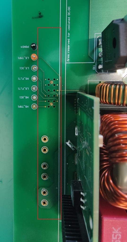
- Connect the Daughter Card to PMP23069 as Figure 1-1 shows. Figure 1-2 shows the area for connection on the mother board.
- Place the PMP23069 inside a ventilated HV safety box.
- Connect the AC power supply to the input connector of the PMP23069 and the Electronic load to the output connector.
Figure 1-1 Test Setup (View
1)
 Figure 1-2 Test Setup (View
2)