TIDT253 January   2022


  1.   Description
  2.   Features
  3.   Applications
  4. 1Test Prerequisites
    1. 1.1 Key System Requirements
  5. 2Testing and Results
    1. 2.1 Sensed VCR and Output Voltage Ripple Under Different Loads
    2. 2.2 Control Loop Bode Plot Comparison
    3. 2.3 Transient Response Test
    4. 2.4 References

Sensed VCR and Output Voltage Ripple Under Different Loads

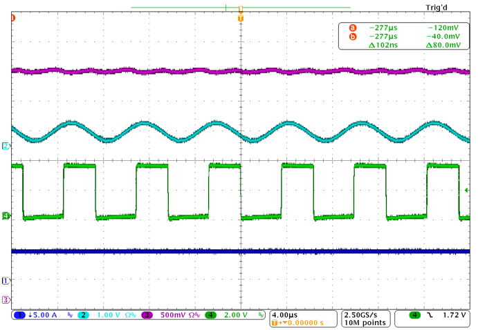
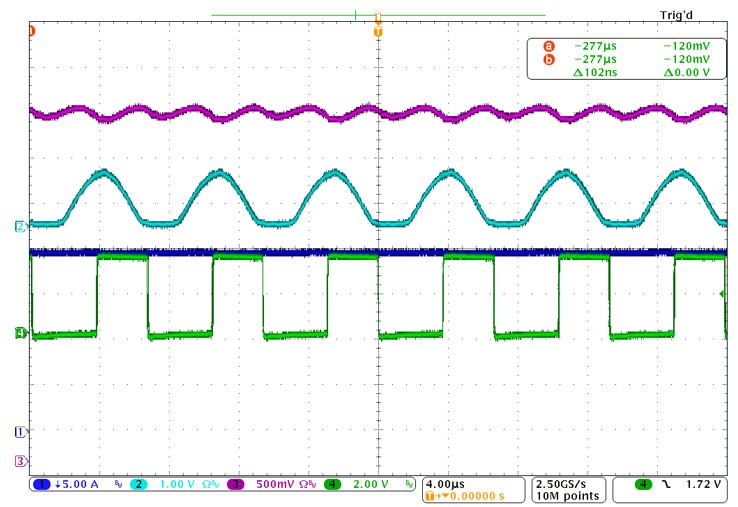
The following parameters apply to Figure 2-1 and Figure 2-2.

  • CH1: output current
  • CH2: VCR feedback signal
  • CH3: output voltage
  • CH4: PWM1A output
GUID-20211208-SS0I-QGSX-3ZJH-HMFLPF3DMW0B-low.png Figure 2-1 Load Current Equals 20 A (24% Load)
GUID-20211208-SS0I-WBHQ-ZF0K-VVBNFX3MTZG8-low.png

Figure 2-2 Load Current Equals 50 A (60% Load)