SSZTBD7 august 2016 LM4041-N , TLV431
Adjustable voltage references offer great flexibility to circuit designers because the reference is not limited to the manufacturer’s pre-set values. The adjustable output is typically configured with a voltage divider from the output to the feedback pin, as shown in Figure 1. To regulate the output, compare the voltage at the feedback pin to an internal reference (shown in this post as VREF_INT), typically 1.2V. The device adjusts the output until VFB and VREF_INT match.
Some adjustable shunt references such as the LM4041 maintain VFB across R1; some maintain VFB across R2, such as the TLV431. I’ll concentrate on the LM4041, but the concepts apply equally to other adjustable shunt references by switching R1 and R2 in the equations. In this blog post, I’ll describe one possible method of changing the resistor divider and in turn changing the reference voltage with digital signals.
 Figure 1 Typical vREF
Feedback Divider
Figure 1 Typical vREF
Feedback DividerThe method involves replacing the two fixed resistors with a single digital potentiometer. Figure 2 demonstrates this conceptually, where the feedback pin is connected to the wiper of the potentiometer and the high and low side are connected to VREF and GND, respectively.
 Connected to Feedback") Figure 2 Potentiometer Center Tap
(Wiper) Connected to Feedback
Figure 2 Potentiometer Center Tap
(Wiper) Connected to FeedbackFigure 3 shows the circuit redrawn, with the TPL0102 digital potentiometer acting as the voltage divider. You can configure a digital potentiometer to act as a voltage divider by connecting a voltage across the high and low pins of the internal resistor and connecting the output to the wiper pin. The wiper position affects the ratio of the resistance between the wiper and the high and low pins, and its position is controlled digitally by sending a code word to the device. The TPL0102 uses an I2C interface, while other potentiometers are available with serial peripheral interface (SPI) or parallel interfaces.
 Figure 3 VREF With the
TPL0102 Digital Potentiometer as the Feedback Divider
Figure 3 VREF With the
TPL0102 Digital Potentiometer as the Feedback DividerBecause the ratio of the resistances sets the output voltage, the absolute values of the divider resistors are not critical. This allows you to easily replace the resistor divider with a digital potentiometer. Equation Figure 1 illustrates the relationship between the adjusted output, VREF_OUT and the resistance ratio:
") Figure 4 (1)
Figure 4 (1)That is an important point in this application, as the absolute resistance value of digital potentiometers can vary quite a bit, while the ratio of the resistances is very accurate. For example, to generate a 3.3V reference voltage, the required resistance ratio of R2-to-R1 is 1.66.
The potentiometer data sheet provides the formulas to calculate the output of the voltage divider for a given code, shown in Equations 2 and 3. VHW is the voltage from the high pin (H) to the wiper (W), while VWL is the voltage from the wiper (W) to the low pin (L):
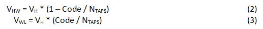
VFB is across R1, as I mentioned in the introduction, so let’s continue with Equation 2, which calculates the voltage between the high pin and the wiper pin. The wiper is connected to the feedback pin of the device, and VFB is forced to VREF_INT. Equation Figure 1 shows the formula solved for the digital code required for VREF_OUT:
") Figure 5 (4)
Figure 5 (4)Continuing the example in Equation Figure 1 where NTAPS is 256, VREF_INT is 1.24V and VREF_OUT is 3.3V, you’ll need to write decimal code 160, which yields resistance values for R1 and R2 of 37.50kΩ and 62.50kΩ, respectively. More importantly, the ratio of these two resistances is 1.66, also calculated using Equation Figure 1:
") Figure 6 (5)
Figure 6 (5)If you need to change the reference voltage, you simply need to write an I2C transaction to move the wiper position accordingly. As a result, the voltage at the feedback pin changes and adjusts VREF_OUT. You can also use the potentiometer to digitally tune the reference voltage, where the greater the number of taps in the potentiometer, the finer the resolution in the resistance ratio and therefore the finer the resolution in the output reference voltage.
A limitation of using a digital potentiometer in this application is the voltage limit of the digital potentiometer integrated circuit (IC), which typically cannot exceed 5.5V. Confirm that the resistance ratio does not get set to a condition that would present a VREF_OUT greater than 5.5V. For a 256-tap digital potentiometer and a shunt reference with an internal reference of 1.24V, the decimal code should not exceed 200. Figure 7 demonstrates the effect of the input code on the reference voltage for a 256-tap potentiometer and a 1.24V-referenced device.
 Figure 7 Reference Voltage vs. Digital
Potentiometer Code
Figure 7 Reference Voltage vs. Digital
Potentiometer CodeEnable and configure the potentiometer before powering the shunt reference to ensure that the resistor divider is correctly in place. If that is not possible, you can add a large resistance in parallel with the resistor that is not acting as the drop for VFB. That would be 1MΩ from the feedback pin to ground (across R2) for the LM4041, or 1MΩ from the feedback pin to the output (across R1) for the TLV431.
To avoid an extra parallel resistance, you can configure the device with fixed R1 and R2 resistors and a digital potentiometer in series with one of them. You would then have to configure the potentiometer as a rheostat, shown in Figure 8. This configuration depends on the absolute resistance of the digital potentiometer, which is not as accurate as when using it as a ratiometric voltage divider, and requires feedback to the microcontroller for final digital-code selection.
 Figure 8 Fixed Resistors with Digital
Potentiometer as a Rheostat
Figure 8 Fixed Resistors with Digital
Potentiometer as a RheostatNow that you understand how an adjustable voltage reference sets it output voltage, you know how to use this to your advantage to change the output voltage dynamically. If the application already uses a microcontroller, including a digital potentiometer can add some versatility to a seemingly simple part.
Additional Resources
- Learn more about TI’s voltage reference products.
- Download the white paper, “Voltage Reference Selection Basics,” for a detailed explanation of voltage-reference selection with respect to analog-to-digital converter (ADC) resolution.
- Read the Open Systems article, “Shunt vs. series: How to select a voltage reference topology.”
- Read TI’s blog series, “Understanding Voltage References,” which discusses the applications of both shunt and series references and when to use them.
- Start your design in WEBENCH® Power Designer.