SSZTBC1 May 2016 AM3357 , AM3359
This is the fifth installment of “How to select the right industrial Ethernet standard,” a series for designers who have decided to leverage industrial Ethernet in their systems. In this series, I’m covering several common industrial Ethernet communication protocols to help you select the right standard for your application. In my previous posts, I discussed EtherCAT, Sercos III, PROFINET and EtherNet/IP.
In this installment, let’s look at Ethernet POWERLINK (which I’ll just call POWERLINK), another one of the top five industrial Ethernet standards for process- and factory-automation applications. Bernecker + Rainer Industrie-Elektronik, an Austrian industrial electronic company, developed POWERLINK and introduced the standard to the market in 2001. Since 2003, the Ethernet POWERLINK Standardization Group (EPSG), an organization that drives specifications and coordinates conformance testing, has controlled the POWERLINK standard.
(One clarification that I would like to make is that sometimes developers get confused about the name POWERLINK. This standard is not related to the Power over Ethernet (PoE) standard, and POWERLINK does not source power to its network components over an Ethernet cable.)
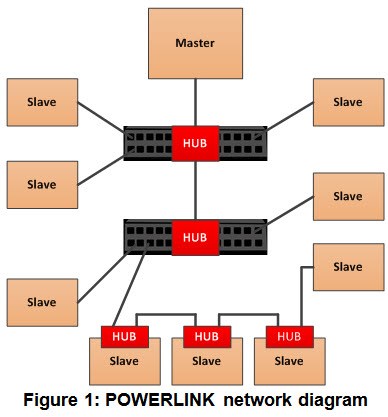
POWERLINK supports a very flexible network architecture, including line and star topology as well as a mixture of both – see Figure 1. Slaves are equipped with one or two Ethernet ports. An Ethernet hub device, which is used for star topologies, must have a specific forwarding time of less than 500ns. This means that any frame gets forwarded to all other hub ports regardless of the Ethernet frame content. Thus, you can’t use standard Ethernet switch devices in a POWERLINK network – a switch device first analyzes the header of an Ethernet frame before making any forwarding decision, and the time it takes for the switch device to make the forward decision is typically in the range of 5 to 10ms. That time is just too long and adds too much frame jitter for a POWERLINK network to operate efficiently.
POWERLINK supports 100Mbps Ethernet with half-duplex transmission only. Therefore, the protocol leverages a master-to-slave polling mechanism to avoid unpredictable frame collisions, where devices could transmit at the same time. PROFIBUS uses a similar approach, where the master sends out a poll-request (PReq) frame, and only the slave addressed by that frame replies with a poll-response (PRes) frame.
POWERLINK uses broadcast frames to ensure that all slaves receive the frame. This requires that each slave receive and process all the protocol's frames, even those not addressed to that slave. Each slave has a frame filter inside the media access controller (MAC) to check for slave-specific address parameters; otherwise the host processor in the slave would suffer from the total frame-processing load.
The MAC also supports an auto-reply feature, where it responds with a pre-defined PRes frame from its local memory. Processing the PReq frame in a standard way by going through several levels of software on the host processor would introduce unpredictable delays and therefore jitter on the POWERLINK network. As such, the systems require an auto-reply feature, and the MAC level answers any PRes frame in the system with minimum delay and jitter.
The POWERLINK communication profile is based on CANopen. It uses process data objects (PDOs) for process variables, and service data objects (SDOs) for configuration and remote objects.
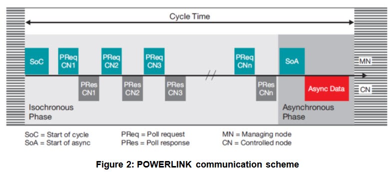
Figure 2 shows a POWERLINK cycle. The master is called managing node (MN) and the slave is called controlled node (CN). The start of the isochronous phase is indicated by the CN with a start-of-cycle frame. During the isochronous phase, the MN controls the bus and therefore defines the timing for each slave. Each CN is cyclically polled with a PReq during the isochronous phase. Each slave responds with a PRes. Real-time critical data PDOs transfer at both times. Once the isochronous phase has ended, the MN sends out a start-of-asyncrounous frame, after which slaves can send any kind of Ethernet-based data. When the cycle time is over, the procedure repeats.
Today’s POWERLINK solutions are commonly based on application specific integrated circuits (ASICs) and field programmable gate arrays (FPGA) implementations with an external host processor, which handles the stack and the industrial application.
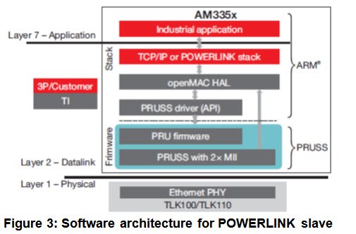
TI’s Sitara™ processors have a solution for POWERLINK (see Figure 3), which supports cut-through hub technology with the unique programmable real-time unit and industrial communication subsystem (PRU-ICSS) peripheral. EPSG has conformance-certified the solution.
The openMAC module, which is a standard Ethernet MAC with extensions for Powerlink, is part of the PRU-ICSS firmware. The PRU-ICSS firmware supports auto-reply and time-triggered send functions. PRU firmware also handles the RX filters, which are then applied to the received Ethernet frame before sending an interrupt indication to the ARM application processor. This minimizes ARM processor load, as the PRU-ICSS firmware sends only the relevant frames to the ARM.
I hope I’ve shed some light into POWERLINK functionality. Be sure to read the other posts in this series to learn more about common industrial Ethernet standards.
Additional Resources
- Explore the TI Designs Ethernet POWERLINK Development Platform Reference Design.
- Explore additional industrial communication protocol solutions for TI Sitara processors.
- Download the “Industrial Communication Solutions Guide.”
- Learn more about the Ethernet POWERLINK standard on the EPSG website.
Other blog posts in the "How to select the right industrial Ethernet standard" series: