SSZTAL6 november 2016 TPD1E01B04 , TPD6S300 , TPD8S300 , TUSB1046-DCI , TUSB546-DCI
If you are a designer tasked with migrating the USB ports in your system to the latest USB standard and USB Type-C connector, you have likely already considered a couple of things.
ESD Protection
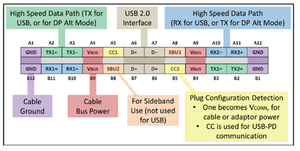
 Figure 1 A Full-featured USB Type-C Plug-in Pinout
Overvoltage Protection
System protection at the connector with OVP and IEC ESD protection is necessary, but a full USB Type-C port-protection solution should enable your system to comply with the specifications of the new USB standard. For example, if your system takes advantage of the new capabilities of USB Type-C, such as supporting SuperSpeed communication, the USB Type-C specification requires VCONN support on the CC lines to power the active cable. For an OVP solution to function on the CC lines, it must support passing a 5.5VDC power rail. The port protection also must have low on-resistance (RON) to ensure that the total voltage drop on the power rail does not exceed what the USB specification requires.
If your system is battery-powered, relying on a Type-C connector as the power source, the solution has to protect the CC lines from an overvoltage condition even in the case of a dead battery.
These and other complex scenarios make a robust solution to protect a USB Type-C port not as straightforward as adding an ESD protection diode and an OVP FET. The OVP FET needs to withstand the clamping voltage given by a high-voltage discrete TVS diode, which makes the FET costly and bulky with a lower RON requirement. This makes the discrete implementation complex and costly, while consuming a large footprint around the tight dimensions of the USB Type-C connector.
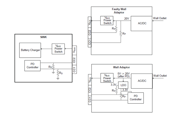
Finally, if you are reading this and thinking to yourself, “My system is straightforward because it does not support the higher wattage (>15W) PD capability and is fully compliant to the specification for <15W PD,” note that a large percentage USB Type-C cables and adapters in the market have been found to be noncompliant to the standard, while others can be faulty (Figure 2). Even in a 5V system, there is a risk that a short-to-VBUS up to 20V can occur before a PD negotiation with the controller. Just like that, the system is damaged and your product’s reputation is compromised.
 Figure 2 CC Pin Exposure for Regular and Faulty Wall Adapters
To learn more about the design considerations for USB Type-C port protection, read “Circuit Protection USB Type-C™.” Integrating a device from TI’s family of USB Type-C port protectors, such as the TPD8S300 or TPD6S300, removes the complexity that comes from migrating your USB ports to the new USB Type-C connector.
Additional Resources
- Download the TPD8S300 or TPD6S300 data sheets.
- Read this Analog Wire blog post to “Learn what challenges to avoid when implementing USB Type-C™ protection.”
- Start designing now with the TPD8S300 evaluation module.
- Check out the TPD1E01B04 single-channel ESD protection diode for super-speed data lines.
- Learn more about the TUSB1046-DCI and TUSB546-DCI USB Type-C Alternate Mode linear redrivers.