SSZTAL3 november 2016 LMX2592 , LMX8410L , TRF370315 , TRF370317 , TRF370333 , TRF370417 , TRF3705 , TRF3710 , TRF371109 , TRF371125 , TRF371135 , TRF3722 , TRF37T05
Let’s say that you have already spent some time optimizing your phase-locked loop (PLL) by iteratively massaging the phase margin and loop bandwidth. Unfortunately, you may still be unable to get a good compromise between phase noise, spurs and lock time. Frustrated? Ready to give up? Wait! Have you ever played around with the gamma optimization parameter?
Gamma Optimization Parameter
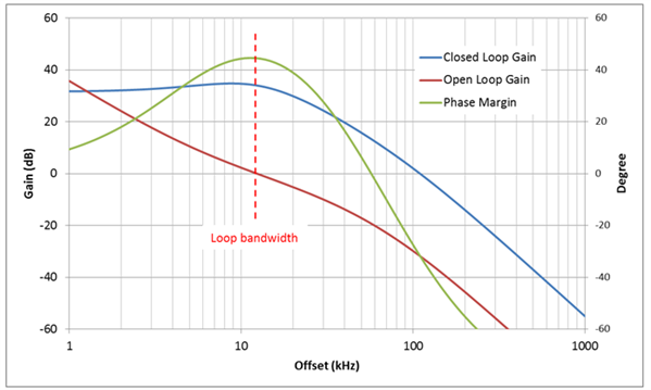
 Figure 1 Bode Plot with Gamma Equal to 1
Gamma is useful in optimizing in-band phase noise, especially peaking due to the voltage-controlled oscillator (VCO). Furthermore, if you are not able to get a higher loop bandwidth due to phase-detector frequency constraints and charge-pump current, gamma will help you unlock the maximum achievable loop bandwidth. Unfortunately, if you make gamma large, it degrades lock time severely.
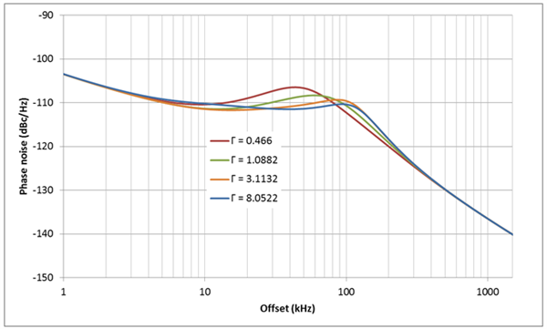
Figure 2 shows the effect of gamma on phase noise. Loop bandwidth and phase margin are the same, while gamma is different. With a higher gamma, the peaking of the VCO will be smaller because the flatness of the noise-shaping loop filter increases.
 Figure 2 Phase Noise vs. Gamma at 1.0882 (a); Phase Noise vs. Gamma at 3.747 (b)
Figure 3 shows the maximum achievable loop bandwidth vs. different gamma values with a second-order loop filter. The phase-detector frequency as well as the charge-pump current remain unchanged.
 Figure 3 Loop Bandwidth vs. Gamma
If the design target is a 100kHz loop bandwidth with a 45-degree phase margin, when gamma is restricted to 1, you can only get a maximum loop bandwidth of 79kHz. However, if you can accept a higher gamma – for example, gamma equals 8 – you will be able to meet the design target. Now the loop bandwidth becomes 96.6kHz with a 43.4-degree phase margin.
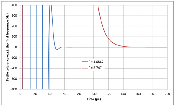
There is a penalty for a higher gamma: a longer required lock time. Figure 4 shows the lock time of a 200MHz frequency jump with different gamma values; loop bandwidth and phase margin are unchanged. When the gamma and loop bandwidth equal 1 and 3.7 and the settle tolerance is within ±100Hz, the simulated lock time values equal 46.5µs and 118µs, respectively.
 Figure 4 Lock Time vs. Gamma
Use Case Example
Additional Resources
- Download the LMX2592 data sheet.
- Check out these design tools: