SSZTAH8 january 2017 LMX2582 , LMX2592 , LMX8410L , TRF370315 , TRF370317 , TRF370333 , TRF370417 , TRF3705 , TRF3710 , TRF371109 , TRF371125 , TRF371135 , TRF372017 , TRF3722 , TRF37T05
“You are what you eat” is a commonly heard saying that recommends the careful selection of food, given its ability to directly affect our health and well-being.
Although not an exact comparison, the concept applies if you think of your input reference signal as the food, ingested by the phase-locked loop (PLL)/synthesizer, which affects the well-being of the PLL/synthesizer, as evident in the output phase noise, shown in Figure 1. In this post, I’ll provide some practical examples to show you what a good input reference looks like, what damage a bad input reference can do and how to analyze a given input reference.
 Figure 1 Input Reference Noise is also
multiplied by the PLL
Figure 1 Input Reference Noise is also
multiplied by the PLLTo back up a little, a PLL, when paired with a voltage-controlled oscillator (VCO), becomes a control-loop system that can lock on to a low-frequency signal (10MHz from a stable crystal oscillator) and multiply it to a much higher frequency (the LMX2592 can multiply up all the way to 9.8GHz).
Example 1
 Figure 2 Low phase noise 100MHz input reference and 5160.96MHz LMX2582 output
Using an input reference like the one in Figure 2 shows the performance of the synthesizer, since the input reference phase noise is low enough. Note that the key region is under the loop bandwidth (~300kHz offset), since beyond this offset frequency the input reference noise is also filtered and will fall in the same manner as the red line (not shown in this example).
Also notice the huge spike at about 120Hz from the input reference. This directly impacts the output phase noise. You can already see the danger here. If noise is coupled somewhere into the input reference source at the lower offsets, it can damage the synthesizer phase noise.
Example 2
 Figure 3 A 122.88MHz input reference and 5160.96MHz LMX2582 output
Example 3
 Figure 4 A noisy 122.88MHz input reference and 5160.96MHz LMX2582 output
To see how this works in an example design, check out our 9.8 GHz RF High Performance Synthesizer Operating From a Buck Converter Reference Design.
Reference Table
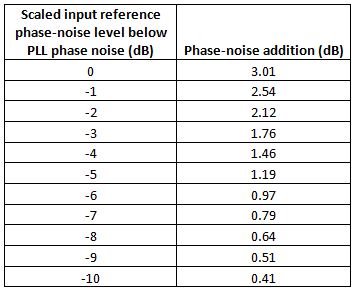
|
With these examples, I hope I’ve shown how a good input reference is vital to getting optimal performance from the synthesizer. A bad input reference is not only one that has too high a phase-noise level, but one that is also more susceptible to external influences (vibration, aging, temperature, power supply). With this information, you should have a better understanding and additional ideas when designing the input reference for your synthesizer. For additional information or if you have questions, visit the TI E2E™ Community High Performance RF Modulators, PLL and VCO forum.
Additional Resources
- Check out TI’s entire PLL/synthesizer portfolio.
- Read the technical article, “A survival guide to scaling your PLL loop filter design.”
- Start designing quickly with the LMX2582EVM high performance, wideband frequency PLLatinum™ RF synthesizer with integrated VCO evaluation module.