SSZTAH1 january 2017 LDC0851
In my last blog post, I discussed how to use inductive switches for proximity applications. In this post, I want to discuss how to use inductive switches in slide switch applications to make circuit breakers more reliable.
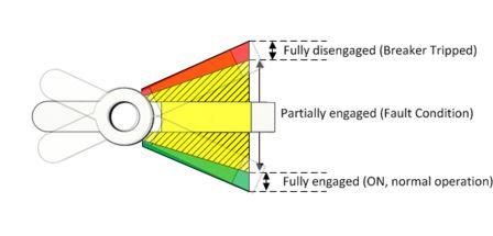
Circuit breakers typically only have two states: on and off. The on state represents the normal operating condition, with electricity flowing through the circuit. Off means that the flow of electricity has been stopped. These two states are usually detected by making resistive or electrical contact with additional electrical contact points on opposing ends of a circuit breaker. This means that a good mechanical system must be in place to ensure that either one or the other state is clearly selected. Over time, the mechanical portion of the switch may wear out, allowing the switch to get stuck halfway or not fully recover after the circuit has been reset. Figure 1 shows an example of the normal engaged/disengaged states as well as the undesirable region in the middle where a typical circuit breaker would fail or improperly work.
 Figure 1 Circuit-breaker States
By using a contactless switching technology such as the LDC0851 differential inductive switch, you can detect the position of the metal lever itself rather than requiring the electrical contact. Thus, if the switch wears down, gets stuck in the middle or creates a partial contact, the LDC0851 will still be able to detect this state and alert users to take action through a simple LED warning or message. Note that this contactless approach also means that the LDC0851 is not affected by any of the AC or DC currents that are flowing in the system.
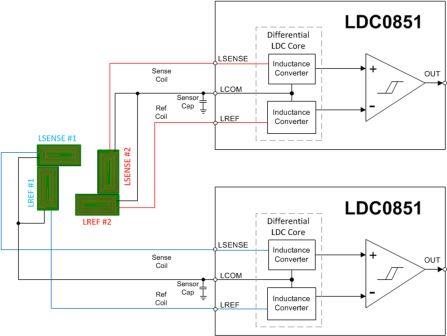
In order to implement this concept I configured two LDC0851 devices, shown in Figure 2.
 Figure 2 Dual LDC0851
Configuration
Figure 2 Dual LDC0851
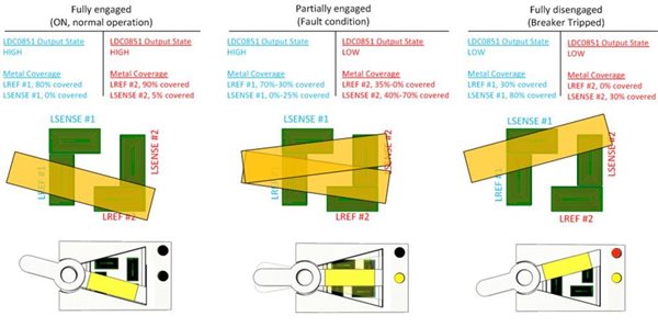
ConfigurationWith the switch fully engaged, both reference coils (LREF #1 and LREF #2) are covered, causing the LDC0851 push/pull outputs to produce a high, high output. When the switch is fully disengaged, both sense coils (LSENSE #1 and LSENSE #2) are covered, causing the LDC0851 push/pull outputs to produce a low, low output. When the switch is anywhere in the middle, representing an unintentional state, LREF #1 and LSENSE #2 are covered, representing a high, low output pattern. These states are represented with a simple yellow and red LED display, but a more sophisticated message display is possible. Figure 3 shows the functional operation.
 Figure 3 LDC0851 Coil-target
Orientation
Figure 3 LDC0851 Coil-target
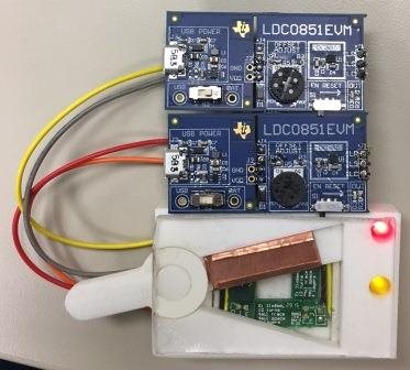
OrientationTo fully test this concept, I 3-D printed a circuit breaker mockup and added copper tape to the lever to simulate a metal target; see Figure 4. I used two of the LDC0851EVMs configured as side-by-side coils with coil E from the LDCCOILEVM. Note that the inductor coils do not make electrical contact with the lever, so they are placed at a nominal 1mm distance from the lever. Additionally, the LDC0851 provides stable operation over temperature and is not affected by environmental contaminants.
 Figure 4 Constructed Circuit Breaker
with LDC0851 Devices
Figure 4 Constructed Circuit Breaker
with LDC0851 DevicesTo see this demo in action, as well as how to expand this concept for other applications, please watch this video.
So when your circuit breaker gets stuck in the middle, you now know that you can solve this problem with TI’s contactless inductive switches. What are your experiences designing with inductive switch applications? Log in to comment below.
Additional Resources
- Learn more about TI’s inductive sensing portfolio and explore the site’s Tools and software, Technical documents, and Support and training tabs.
- Read these relevant inductive sensing blogs: