SSZTA76 may 2017 LM5175 , LM5175-Q1

An automotive battery’s steady-state voltage ranges from 9V to 16V depending on its state of charge, ambient temperature and alternator operating condition. However, the battery power bus is also subject to a wide range of dynamic disturbances, including start-stop, cold crank and load-dump transients.
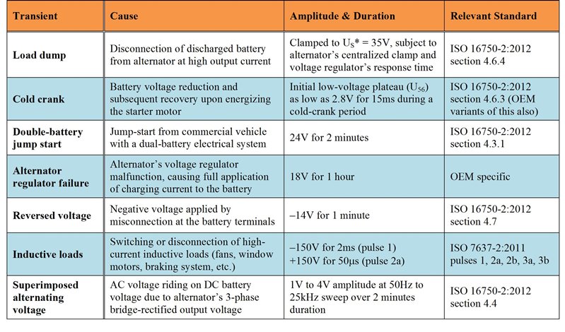
Each automotive manufacturer has a unique and extensive conducted immunity test suite in addition to the standardized pulse waveforms given by industry standards such as International Organization for Standardization (ISO) 7637 and ISO 16750. Table 1 identifies several undervoltage and overvoltage automotive transient profiles.
|
Alternator-induced Noise
; a Log Frequency Sweep Profile from 50Hz to 25kHz over a Two-minute Sweep Duration (b)") Figure 1 An ISO 16750-2 Superimposed Alternating Voltage Test (a); a Log Frequency Sweep Profile from 50Hz to 25kHz over a Two-minute Sweep Duration (b)
Figure 1 An ISO 16750-2 Superimposed Alternating Voltage Test (a); a Log Frequency Sweep Profile from 50Hz to 25kHz over a Two-minute Sweep Duration (b)In many vehicles, a centralized passive-circuit-protection network consisting of a low-pass inductor-capacitor (LC) filter and transient voltage suppressor (TVS) diode is used as a first line of defense for transient disturbance rejection. Automotive electronics located downstream from the protection network are then rated to survive transients up to 40V without damage. However, the required cutoff frequency of the LC filter to attenuate low-frequency disturbances makes the filter inductor and electrolytic capacitor quite large. What’s required is an active power stage that eliminates the bulky passive filter components and provides a compact and cost-effective solution for tight voltage regulation and transient rejection.
Four-switch Synchronous Buck-boost Regulator
 Figure 2 Four-switch Synchronous Buck-boost Solution with a Wide VIN Range of 3V to 36V
Figure 3a shows the buck-boost regulator’s output voltage waveform when a DC input of 9V has a superimposed sinusoidal ripple with a peak-to-peak amplitude of 1V and a frequency of 1kHz. The input ripple is attenuated by approximately 40dB. Figure 3b shows the output voltage during a cold-crank transient down to 3V for 20ms using an automotive cold-crank simulator. The four-switch buck-boost converter regulates seamlessly through the cold-crank profile.
; Cold-crank Performance (b)") Figure 3 Measured Four-switch Buck-boost Converter: Ripple Rejection at a 9V DC Input (a); Cold-crank Performance (b)
Figure 3 Measured Four-switch Buck-boost Converter: Ripple Rejection at a 9V DC Input (a); Cold-crank Performance (b)Summary
Additional Resources:
- Check out the “Under the Hood of a Non-Inverting Buck-Boost DC/DC Converter” topic from TI’s 2016-2017 Power Supply Design Seminars.
- Read “Designing the front-end DC/DC conversion stage to withstand automotive transients” in the 1Q17 edition of TI’s Analog Applications Journal.
- Order an evaluation module for the LM5175-Q1 buck-boost controller.
- Peruse the ever-expanding repository of wide VIN automotive power solutions in the TI Designsreference design library, for example: