SSZTA19 july 2017 UCC28180
As losses in the grid increase due to bad power factor (PF), mandates call for more and more end equipment to comply with stringent target values. Air conditioners are already fully regulated, but other motorized appliances such as ceiling fans, vacuum cleaners or refrigerators will likely be next.

Power-supply unit (PSU) efficiency enhancement has been an important research goal in the development of systems that consume significant amounts of power. Because medium- and high-capacity PSUs with power ratings of hundreds of watts or more require high power-factor performance, such devices have two-stage structures that include a power factor correction (PFC) circuit.
The efficiency of the PFC power stage is important to overall PSU performance. PFC circuit performance has continually improved through the use of better switching parts (field effect transistors [FETs] and diodes), the development of improved magnetic parts materials, and the application of circuit structure research. In this post, I’ll explain how to select and design an efficient and cost-competitive PFC choke to improve the efficiency of the PFC power stage.
Figure 1 shows a typical single-phase boost PFC main power stage. In this topology, four things contribute most to consumption:
- Bridge diode loss.
- Inductance loss, including core loss and copper loss.
- Freewheeling diode loss, including conduction loss and reverse-recovery loss (the latter only generated under continuous conduction mode [CCM]).
- Switching device losses, including switching loss, conduction loss and drive loss.
Figure 1 shows what parameters from the PFC stage have influence on efficiency. Next we’ll discuss how to select a suitable magnetic material in a PFC choke design that improves efficiency, yet is cost competitive.
 Figure 1 Typical Single-Phase Boost PFC
Main Power Stage
Figure 1 Typical Single-Phase Boost PFC
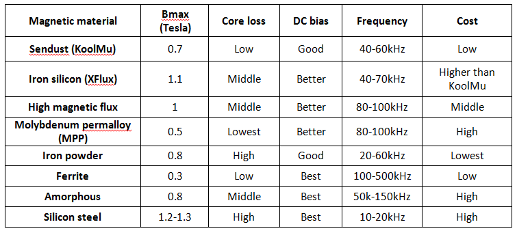
Main Power StageUsually, the magnetic core is classified into alloy-type cores and ferrite cores, with the alloy-type core including iron powder cores, sendust cores, and iron-nickel alloy and amorphous cores. Different magnetic materials have different features: a ferrite core has a high micro value so you can get high inductance easily, but it is also easily saturated. An alloy-type core has soft saturation characteristics, which means that it would not be saturated even if it passed a short current, a feature very useful in some applications. Table 1 compares the different magnetic materials.
|
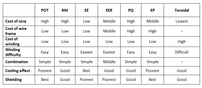
Different magnetic core shapes have different characteristics, such as cost, thermal and shielding characteristics. Table 2 compares the key features between different shapes.
|
When you start a new design, you should first know what your main goal is: high efficiency, low cost or small form factor. Different requirements determine which magnetic material you should choose to achieve the best performance.
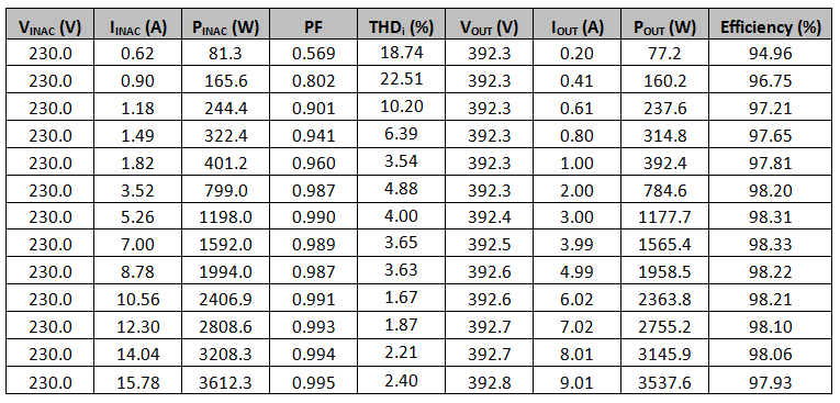
The 230-V, 3.5-kW PFC with ≥98% Efficiency, Optimized for BOM and Size Reference Design is a TI design especially suitable in appliance applications like air conditioners. In this reference design, I used the sendust core as the PFC choke. I chose 45kHz as the main switching frequency, because at this frequency, a sendust core has the best balance of cost and efficiency, so I can get very high efficiency at a high line input.
Table 3 shows the efficiency test results under 230VAC and 270VAC inputs, respectively. Also, because sendust cores have the characteristic of soft saturation, they avoid the risk of short circuits on the main switch.
|
From these tables, you can see that it’s possible to approach 98.6% peak efficiency at a high line input without using any expensive components like silicon carbide (SiC) diodes.
Figure 2 shows a line-frequency PFC choke current under a 230VAC input; the shape is the same as the input voltage. Figure 3 shows a switching-frequency PFC choke current under a 230VAC input. From this picture, you can see that there is almost no ring noise when the switch turns on and off, which helps with electromagnetic interference (EMI) performance.
 Figure 2 Line-Frequency PFC Choke
Current Under a 230-VAC Input
Figure 2 Line-Frequency PFC Choke
Current Under a 230-VAC Input Figure 3 Switching-Frequency PFC Choke
Current Under a 230-VAC Input
Figure 3 Switching-Frequency PFC Choke
Current Under a 230-VAC InputAs mentioned earlier, the increased stringent power requirements in home appliances are requiring better PFC solutions. The 230-V, 3.5-kW PFC with ≥98% Efficiency, Optimized for BOM and Size Reference Design shows designers how to build an efficient PFC stage still being optimized for cost and size.
Additional Resources
- Learn more about the UCC28180 8-pin Continuous Conduction Mode (CCM) PFC controller