SSZT913 october 2017 TLV61046A
A piezoelectric buzzer is a loudspeaker that uses the piezoelectric effect to generate sound. Its lightweight, simple construction and low price make it usable in many applications, such as home appliances, shared bikes and alarm devices. A typical piezoelectric buzzer is made of piezoelectric ceramic adhered to a metal plate. The plate is normally placed into a plastic case to improve sound press.
Piezoelectric ceramic is a man-made material that harnesses the piezoelectric effect discovered in 1880 by Jacques and Pierre Curie. Applying an oscillating electrical field causes the ceramic material to stretch or shrink. The deformation of the ceramic material causes a metal plate to bend in two directions and generate sound waves in the air, as shown in Figure 1. Assembling the plate into a plastic case can improve the sound pressure of a buzzer.
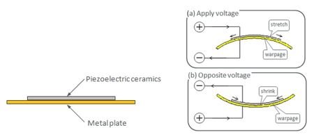 Figure 1 Operating Principle of a
Piezoelectric Buzzer
Figure 1 Operating Principle of a
Piezoelectric BuzzerA piezoelectric buzzer has the highest sound pressure when driven with a frequency equal to its resonant frequency. Thus, it is normally used in applications where volume and high-pitch requirements are more important than sound quality. In a shared bike application, a piezoelectric buzzer is used in the smart lock to indicate lock status clearly despite conditions like a noisy street. The function of the buzzer as an alarm device or in a home appliance is identical.
In a piezoelectric buzzer, the sound pressure mainly depends on the voltage amplitude if driven with a resonant frequency. The higher the driving voltage, the higher the sound pressure. Taking Murata’s PKM13EPYH4002 as an example, the maximum driving voltage amplitude, 30V, generates the highest sound pressure. But the battery in a shared bike smart lock or alarm device is normally a one-cell lithium-ion battery or an alkaline battery in series. The battery voltage is not higher than 4.2V – much lower than the voltage requirement. Thus, a boost topology circuit is required to convert the voltage. In addition, the boost circuit should have a small shutdown current in order to extend battery life. A piezoelectric buzzer is off most of the time and only powers on when necessary.
The input voltage of TI’s TLV61046A ranges from 1.8V to 5.5V, which covers two alkaline batteries in series, a lithium-ion battery and a 3.3V, 5V bus power system. The maximum output voltage is 28V with 29V of overvoltage protection (OVP). The OVP function can protect the boost converter and load from damage when the feedback resistor divider is incorrectly soldered during manufacture.
The input peak current of the TLV61046A is set to 980mA, which is high enough to drive a piezoelectric buzzer. The cycle-by-cycle current-limit and short-circuit protection functions protect the converter and power supply during short-circuit conditions.
The TLV61046A also integrates a power rectifier diode and an isolated metal-oxide semiconductor field-effect transistor (MOSFET). The rectifier diode eliminates the external Schottky diode found in traditional high-voltage boost converters and reduces cost and solution size. The isolated MOSFET disconnects the current path from power supply to load when the device is disabled to reduce current consumption. Because of its high level of integration, the implementation of a TLV61046A boost solution is simple, as shown in Figure 2.
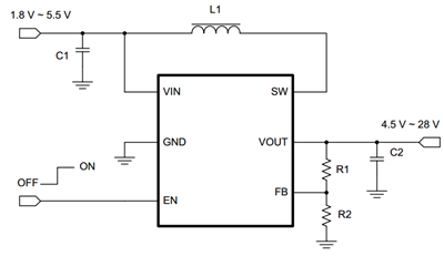 Figure 2 TLV61046A Schematic
As I mentioned above, an oscillating voltage is required to drive a piezoelectric buzzer. An N-channel P-channel N-channel (NPN) transistor can generate the oscillating voltage, as shown in Figure 3. The output voltage of the TLV61046A is set to a maximum of 28V. LS is the piezoelectric buzzer. The pulse-width modulation (PWM) is the signal from an input/output (I/O) pin of a microcontroller. The frequency of the PWM signal should be equal to the resonant frequency of the buzzer if you need the highest sound pressure. R4 limits the output current of the I/O pin. When the PWM signal is higher than 0.7V, Q1 turns on and LS charges to 28V. When the PWM signal is zero, Q1 turns off and R3 discharges LS. The voltage across LS is a rectangular waveform during operation, as shown in Figure 4.
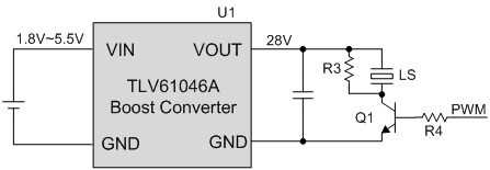 Figure 3 Simplified Schematic of a
28V Piezoelectric Buzzer Driver
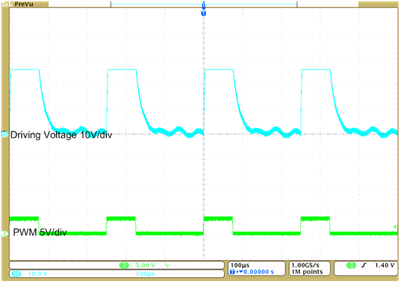 Figure 4 Operating Waveform of a
28V Piezoelectric Buzzer Driver
Figure 4 Operating Waveform of a
28V Piezoelectric Buzzer DriverDriving the piezoelectric buzzer with a voltage amplitude of ±15V or higher is also possible with the TLV61046A; Figure 5 shows the simplified schematic to generate this voltage. The output voltage is set to 15V. An easy charge-pump circuit based on diodes outputs 30V. Q1 and Q2 form a totem-pole circuit to drive the negative side of LS with approximately 30V or 0V. Thus, the voltage across LS is a ±15V rectangular waveform.
Figure 6 shows the operating waveform of this circuit. By setting the output voltage of the TLV61046A to 28V, the driving voltage of the buzzer can be as high as ±28V, which greatly increases the sound pressure.
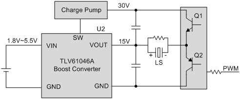 Figure 5 Simplified Schematic of a
±15V Piezoelectric Buzzer Driver
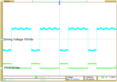 Figure 6 Operating Waveform of a
±15V Piezoelectric Buzzer Driver
Figure 6 Operating Waveform of a
±15V Piezoelectric Buzzer DriverThe TLV61046A highly integrated boost converter has a wide input voltage and as much as 28V of output voltage. Its abundant features make it easy to use not only in piezoelectric buzzer drivers, but also in passive-matrix organic light-emitting diodes (PMOLEDs), high-side MOSFET drivers and liquid-crystal display (LCD) panels.
For more details about the circuit and test bench data discussed in this post, check out the High Voltage Cost-Effective Piezoelectric Sounder Driver Reference Design.