SSZT902 November 2017
Field-programmable gate arrays (FPGAs) are used in applications ranging from medical devices, to wire communications, to aerospace and defense. FPGAs simplify the design process by providing a reprogrammable circuit; this ability to repeatedly reprogram enables quick prototyping and eliminates the need to create a custom application-specific integrated circuit (ASIC). FPGAs are a relatively inexpensive solution even in small quantities, making them popular at both small and large companies. However, because of the multiple rails required to power the FPGA (as shown in Figure 1), it can be confusing to design the power circuitry.
 Figure 1 Basic FPGA Schematic
Each rail will have different requirements for current, accuracy, voltage ripple, load transients and sequencing. This means that the power design will require multiple power supplies to meet all of the different rail requirements. In this four-part series, I will break down the basic design considerations of designing FPGA power circuitry, starting with my first topic: system architecture.
The requirements of your application will inform your system architecture. Typically, as shown in Figure 2, designers will use a DC/DC converter to step down from the power source to an intermediate rail. Additional power supplies will then step the intermediate voltage down to the point-of-load (POL) power required.
 Figure 2 Typical System
Architectures
Figure 2 Typical System
ArchitecturesOne of the first steps is deciding what voltage to use for the intermediate rail. The most common intermediate rail voltages are 12V, 5V and 3.3V. Typically, the lower the intermediate rail, the higher the efficiency of the voltage conversion to the POL power level. However, a lower intermediate rail voltage will require a higher input current. There are also fewer devices available that can step down to 3.3V, depending on how high the voltage of the power source is. Table 1 summarizes the trade-offs.
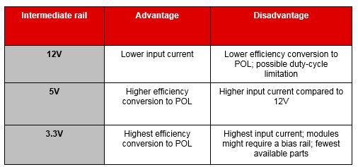
|
Defining the system architecture will determine what devices and how much power you need to feed your design. After selecting the architecture, you can then move on to the next step: determining the current level. To determine the current requirements, I recommend that you use the spreadsheets provided by your FPGA vendor. From these spreadsheets, input the specific FPGA you are using and other details of your design (like clock frequency and temperature) and it will calculate the voltage and current requirements of each rail.
Once you define the system architecture and have estimated the current requirements, it is time to start looking at the requirements of individual rails which will be covered in the next blog post. In the meantime, get more information on TI’s solutions for Xilinx and Altera FPGAs.