How aggravating is it to pick up an electronic device that you’ve barely used, only to find that the battery is nearly or completely dead? If your device was just on standby or asleep, this may have happened because
of a small but crucial specification: quiescent current.
What Is Quiescent Current?
Quiescent is
defined as “a state or period of inactivity or dormancy.” Thus, quiescent current,
or IQ, is the current drawn by a system in standby mode with light or no
load. Quiescent current is commonly confused with shutdown current, which is the
current drawn when a device is turned off but the battery is still connected to the
system. Nevertheless, both specifications are important in any low
battery-consumption design.
Quiescent
current applies to most integrated circuit (IC) designs, where amplifiers, boost and
buck converters, and low dropout regulators (LDOs) play a role in the amount of
quiescent current consumed. In this blog post, I’ll focus on LDOs because of their
simple design and ease in calculating power dissipation. (For those unfamiliar with
LDOs, the application report, “Technical
Review of Low Dropout Voltage Regulator Operation and Performance”
explains them in detail.) When an LDO is fully operational, Equation 1
calculates its power dissipation as:
Equation 1. 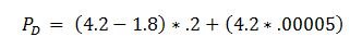
For example, if you needed to drop
from 4.2 V to 1.8 V with 200 mA of output current using an LDO with 0.05 mA of
quiescent current, plugging those numbers into Equation 1
results in a power dissipation (PD) of:
Equation 2. 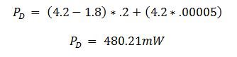
When the application switches to
standby mode or into a light load situation, quiescent current plays a much greater
role in the power dissipated. Continuing from my previous example, if
IOUT becomes significantly lower – 100 µA, for example –
PD becomes:
Equation 3. 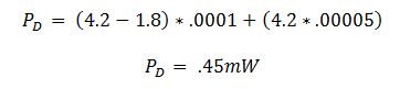
In this example, quiescent current
contributes nearly 50% of the power dissipated.
You might be thinking, “Well, that’s
not that much power being wasted.” But what about applications that spend a majority
of their time in standby or shutdown mode? Smart watches, fitness trackers and even
some modules on a cellphone frequently spend their time in either of those states.
Fitness trackers that don’t keep their display running all the time represent a
light load condition, where the IQ of the LDO used for regulation will
play a significant role in battery life.
Space Constraints and Battery Life
As the trend toward smaller and lighter consumer products continues, engineers face the challenge of decreasing size while maintaining or increasing battery life. In most instances the battery is the largest and
heaviest part of the design; however, designers don’t want to physically shrink the battery because that would decrease both battery capacity and battery life. Therefore, it’s essential to keep all other onboard devices as small as
possible.
Should you be concerned that you’re sacrificing performance for size? The short answer is no. TI has LDOs with peak power performance and small size because thermal resistance doesn’t need to be high for low power
dissipation. The TPS7A02 is a prime example. It boasts a 0.65 mm by 0.65 mm wafer chip-scale size with a 0.35 mm pitch that provides 25 nA of quiescent current. That is not only one of the smallest-sized LDOs, but also one of the lowest
IQ devices on the market. The TPS7A02 is also made in a 1 mm by 1 mm small outline no-lead (X2SON) for designers who don’t need the 0.65 mm by 0.65 mm size. This device and similar LDOs give you the best of both worlds in
terms of size and performance.
Enabling Your Success
An enable or shutdown pin is another simple solution if you’re designing to conserve battery life. Smartwatches, fitness trackers, phones and even drones can employ this solution for a battery boost. Drones – out of
all of the consumer electronics that I mentioned – spend very little time in standby mode because they’re usually only idle pre- or post-flight. You can still save battery life by shutting down LDOs attached to those modules not needed for
flight. Some of these modules include the complementary metal-oxide semiconductor (CMOS) image sensor and gimbal (as shown in Figure 1), since these modules
are only used when the user wants to record videos or take pictures. The shutdown current of the LDO, which is typically a few hundred nanoamps, is then the drain on the battery, which is even lower than the LDO’s quiescent current. This
ultimately can give users a little bit more flight time.
LDOs are also great for the CMOS image sensor and gimbal in particular because both of these modules are sensitive to noise. Any noise reaching the image sensor or gimbal will affect the quality, resolution and
stability of video or pictures taken from the drone.
You can apply this same idea to a phone’s camera, a module that also isn’t on often but still requires a clean, noiseless rail in order to maintain image quality.
Conclusion
Although battery life is highly dependent on the load conditions while running, LDOs with low quiescent current are a simple solution to help boost the runtime of any battery-driven device. These small devices
aren’t just limited to consumer electronics either; they play just as big of a role in industrial applications like building and factory automation. So even though designers sometimes overlook IQ and shutdown current, they could
ultimately make the difference in an application running for a few more seconds, minutes, hours or even days. Now that you have learned the importance of quiescent current, so make sure to always account for it in your power dissipation
calculations.
Additional resources:
 Figure 1 Generic Block Diagram of Drone Modules