SSZT608 october 2018 MSP430FR2355

Temperature, pressure, flow, pH levels – these are some of the variables commonly monitored in process control and factory automation applications. Pneumatic systems originally controlled and monitored these variables until the 1950s, when electronics became more affordable and robust enough to implement. The electronics evolution created a new controlling and monitoring standard for process control applications: 4- to 20-mA current loops.
The general functionality involves using a sensor to monitor an environmental variable – like temperature, gas, light or another condition – and converting it into a current loop ranging from 4 to 20 mA.
(If you are not familiar with current loops, you may be wondering “Why use current instead of voltage?” Using current instead of voltage to quantify a sensor measurement has several advantages. Data from environmental sensors is commonly sent over long distances in process control and factory applications. When introducing long cables into a system, voltage drops can occur; however, there is a greatly reduced risk of signal degradation when using current instead of voltage. Current is also less sensitive to noise than voltage, which can be important in factory environments where motors are present.)
Figure 1 shows a general current-loop design. A sensor monitoring an environmental condition will feed data into an analog-to-digital converter (ADC). This ADC will convert the sensor data to digital data and feed it to a microcontroller (MCU) for processing. Once the data is processed, the MCU will send the digital data to a digital-to-analog converter (DAC). The DAC will then control the current level in the current loop with its analog output and a transistor.
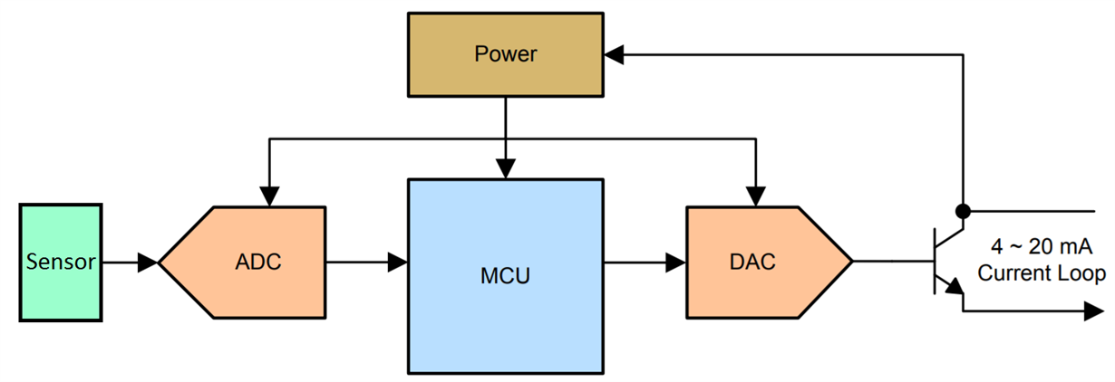 Figure 1 General 4- to 20-mA
Current-loop Transmitter Design
Figure 1 General 4- to 20-mA
Current-loop Transmitter DesignThese current-loop designs call for multiple components. Fitting a sensor, ADC, MCU, DAC and power circuit on a printed circuit board (PCB) can quickly eat up board space and increase bill-of-materials (BOM) costs.
The MSP430FR2355 can help ease these burdens by offering an integrated solution for current-loop designs without sacrificing performance. The Smart Analog Combo is a new peripheral featured on the MSP430FR2355 that provides four configurable analog blocks. Each block includes a 12-bit DAC and an operational amplifier (op amp) with programmable gain amplifier capability.
When using the Smart Analog Combo peripheral, you can take the general current-loop design shown in Figure 1 and reduce it to the configuration shown in Figure 2. This configuration also enables the implementation of isolation if required.
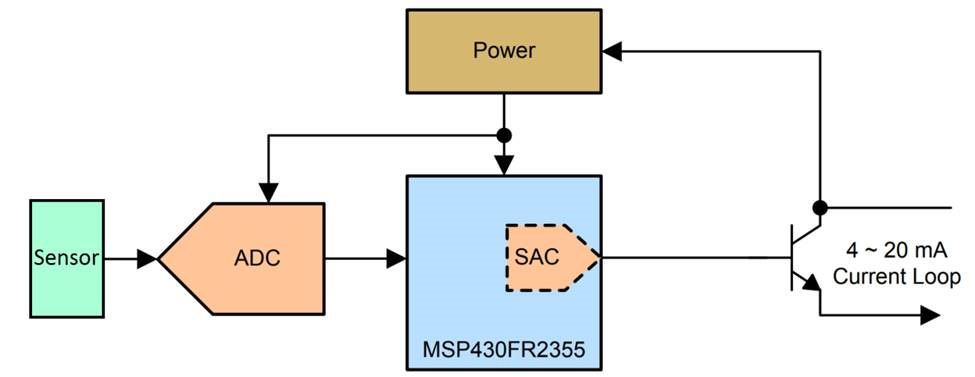 Figure 2 4- To 20-mA Current-loop
Transmitter Design with the MSP430FR2355 Smart Analog Combo Peripheral
Figure 2 4- To 20-mA Current-loop
Transmitter Design with the MSP430FR2355 Smart Analog Combo PeripheralConfiguring the SAC peripheral in a DAC configuration ultimately results in more board space and less BOM costs. Figure 3 shows the functional DAC configuration within the Smart Analog Combo.
 Figure 3 Smart Analog Combo
Current-loop Configuration
Figure 3 Smart Analog Combo
Current-loop ConfigurationThe first Smart Analog Combo block (SAC3) is in a DAC configuration. This block generates a voltage depending on the DAC output. The output of the first block connects to the positive input of the second block (SAC1), which is an op amp configured in general-purpose mode. The SAC1 block controls the gate voltage of the transistor. The current value ILoop depends on the external resistor values and output voltage of the DAC in SAC3. For more information about this design, see the 4- to 20-mA Loop-Powered RTD Temperature Transmitter Reference Design with MSP430 Smart Analog Combo.
Depending on your system’s requirements, it may be possible to further integrate your current-loop transmitter design (and minimize BOM costs) by using the MSP430FR2355’s internal 12-bit ADC. Figure 4 diagrams this integration.
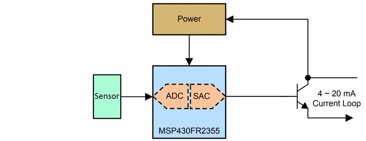 Figure 4 Smart Analog Combo
Current-loop Configuration Transmitter with an Internal ADC
Figure 4 Smart Analog Combo
Current-loop Configuration Transmitter with an Internal ADCIn addition to the smart analog combo, MSP430FR2355 MCUs also come qualified for temperatures up to 105°C, in a small form factor RSM package. This package measures 4x4mm and is nearly 60% smaller than the larger QFN, 6x6mm MSP430FR2355 RHA package (Figure 5). For factory or process control applications, where size constraints may exist, having a high density 32-pin package with integrated analog on-chip for sensing can be greatly beneficial.
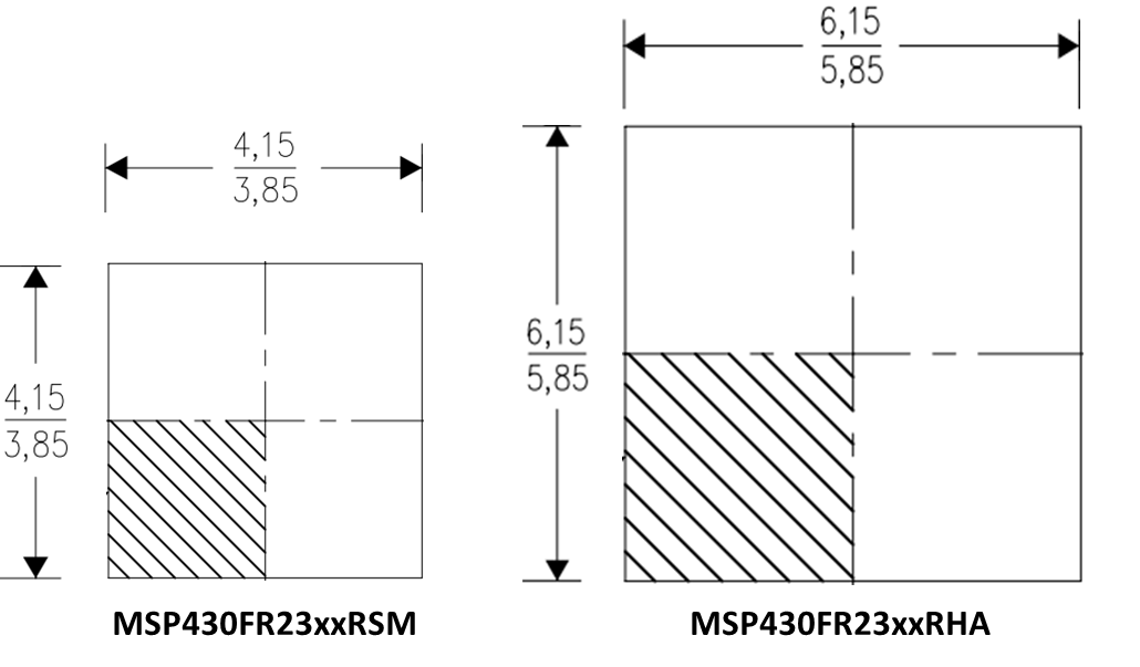 Figure 5 Size Comparison (in Mm) of
32-Pin RSM Package to 40-Pin RHA Package
Figure 5 Size Comparison (in Mm) of
32-Pin RSM Package to 40-Pin RHA PackageThe MSP430FR2355 provides the benefits of saved PCB space and reduced BOM costs – all while providing reliable performance. Current-loop transmitters are one of many systems that can benefit from the added value of the MSP430FR2355.
Additional Resources
-
Download the “MSP430FR2355 LaunchPad Development Kit (MSP-EXP430FR2355)” user’s guide.
-
Learn more about how the “Smart Analog Combo Enables Tomorrow’s MCU-Based Sensing and Measurement Applications.”
-
Check out Dave Smith’s blog post, “Get more signal chain from your MCU in factory automation applications,” where he explains how the 4- to 20-mA reference design can benefit factory automation applications.
-
For more information about the Smart Analog Combo peripheral, check out the “How to Use the Smart Analog Combo in MSP430” application report.