SSZT577 december 2018 DRV8800
Utilities deploy an estimated 100 million smart electricity meters around the world annually. The ability to monitor live power consumption and remotely provide or disconnect electric service to customers is a foundational feature for a smart electricity meter.
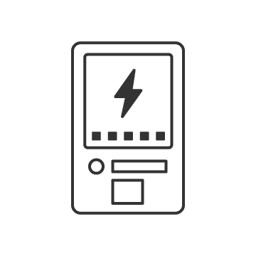
Utility operators need to remotely connect or disconnect electric service for several possible reasons, including new customers moving in, existing customers moving out, emergency or immediate safety concerns, failure to pay bills, or even a service restart recharge of pre-paid accounts (specific to a prepaid meter). An electromagnetic relay, which is an isolated switch operated by a relatively small electric current that can turn a much larger electric current on or off, is used to connect or disconnect utility services.
| Reference designs and products for e-meters | |
|
Learn more about our products and reference designs for electricity meters |
Figure 1 shows the wiring diagram of an electric meter for a home.
 Figure 1 Typical Electric Meter Wiring
Diagram
Figure 1 Typical Electric Meter Wiring
DiagramThere are two types of latching relays used in smart meters: single-coil relays and dual-coil relays.
Single-coil Relay Operation
 Figure 2 Single-coil Relay
Because there is just a single coil, an H-bridge architecture drives the current in the coil in either direction. Figure 3 is a simplified schematic for driving a single coil using an H bridge.
 Figure 3 H-bridge Schematic for Driving a Single Coil
Dual-coil Relay Operation
 Figure 4 : Simplified Block Diagram of a Dual Coil Relay: on Pulse = Contact on, off Pulse = Contact off
Even though both single and dual-coil relays achieve the same end functionality, you need to consider two key factors when selecting the appropriate relay architecture:
- The complexity of the driving circuit.
- A single-coil relay needs high and low-side switches. Driving a single-coil relay requires an H-bridge drive-type configuration.
- The dual-coil relay needs only low-side switches, which are driven directly by a microcontroller (MCU).
- The cost of the relay.
- Single-coil relays are relatively less expensive than dual-coil relays.
- Consider the overall cost with the electronic circuitry driving the relay.
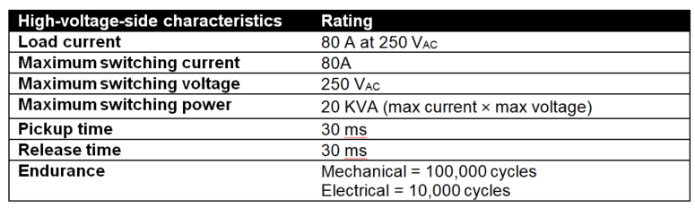
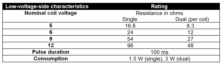
Table 1 and Table 2 show typical characteristics of a latching relay.
|
|
Based on the utility’s requirements for smart meter specifications, you’ll need to choose a suitable relay and its driving electronics circuit. For the low-voltage side in Table 2, as the applied voltage increases, the resistance of the coil also increases. However, in reality, you should interpret this as a reduction in the coil-driving current required to achieve successful toggling. The duration of the pulse is constant, hence the power required.
Single-phase meters can use two relays: one to disconnect the live line and one to disconnect the neutral line. The low-voltage coils of these two relays can be parallel or driven separately, although the second option offers a key advantage: driving the relays separately eliminates the danger of arcing. When moving the live-wire relay to disconnect, the circuit between the line and neutral breaks and the current stops, so there is no chance of the neutral relay being exposed to arc conditions while it is switching between open or closed (see Figure 5).
Thus, alternating between the two relays at every instance of operation doubles the relay life expectancy because of the reduced number of hot operations. As you can see in Table 1, the electrical endurance is 10,000 cycles, but driving the relay separately doubles this expectancy to 20,000 cycles for a given meter.
 Figure 5 Arching Phenomenon in Relay
Connect/disconnect
Figure 5 Arching Phenomenon in Relay
Connect/disconnectTable 2 also shows that the peak power required to operate a relay is in the proximity of 3 W (dual) and 1.5 W (single). Operating the two relays connected on live and neutral in parallel will load the power supply instantaneously with a peak power of 6 W, which can considerably increase the cost of a power-supply design. However, operating the relays one after the other with an internal time gap, coupled with the bulk capacitors, assures an appropriately optimized design for the power supply.
Using a Motor-drive IC for Relay Operation
 Figure 6 DRV8800 Block Diagram
If the current needs to be set up from OUT+ to OUT-, a suitable logic on the input pin (phase) will trigger the turnon of Q1 and Q4 simultaneously. This results in the application of Vcc across the OUT pins with OUT+ on the positive potential. Similarly, to toggle the relay to the other state, you will need to set up a current to OUT- from OUT+. A suitable logic on the input pin (phase) will cause Q3 and Q2 to turn on simultaneously. This results in the application of Vcc across the OUT pins, with OUT- on the positive potential. Thus, current flows across the low-voltage circuit of the coil in either direction by applying a suitable voltage on a single pin at the input of the DRV8800.
One of the most important features of the DRV8800 is overcurrent monitoring. The current flowing through metal-oxide semiconductor field-effect transistor (MOSFET) Q1, Q2, Q3 and Q4 is monitored internally to ensure that the current through any of these MOSFETs doesn’t exceed the set limit, thus protecting the device and the power supply. If a short is detected, the full-bridge outputs turn off, and flag nFAULT, as mentioned in Figure 6, is driven low.
Another important feature is the motor current trip point. When the voltage on the sense pin exceeds VTRIP (0.5 V), an overcurrent is detected (the voltage on the sense pin = Rsense × Isense). The Rsense resistor connected between the sense pin and ground should be sized to set the desired ITRIP level. To prevent false trips, the ITRIP must be higher than the regular operating current. In the event of any damage to the relay or the relay driver, the current through the relay driver will be limited to make sure that the power supply is not affected. Thus, any fault on the relay section does not affect the primary functionality of metrology and wireless communication.
A discrete implementation to drive the latching relays would result in a number of discrete devices, such as a transistor used as a level translator, a main transistor, a freewheeling diode, etc., which would take up more board space and reduce the reliability of the entire system.
As a side note, the same IC can be used for driving a single- and dual-coil relay. The only difference is that a dual coil uses only bottom MOSFETs Q2 and Q4 and a single coil uses the complete H bridge, consisting of Q1, Q2, Q3 and Q4. Alternatively, a dual coil relay can be turned into a single coil relay simply by disconnecting the center tap.
Because these ICs have high-input, impedance-based complementary metal-oxide semiconductor (CMOS) input stages, they give you the advantage of toggling the state of the relay by sending high/low commands directly from the output pin of the MCU. You won’t need a discrete transistor-based level translator as required in the discrete approach.