SSZT188 february 2021 DP83TD510E

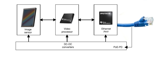
The surveillance infrastructure is steadily increasing across industries, offices and residential buildings to help maximize security. Over the last decade, camera technology has undergone significant technological advancements in terms of image sensors, video processing, connectivity and video analytics through artificial intelligence. Most cameras use the Mobile Industry Processor Interface (MIPI) to connect an image sensor to a video processor, which enables camera upgrades with image sensors of various resolutions. Figure 1 shows various components that make up a video surveillance camera system.
 Figure 1 A basic Internet Protocol (IP)
surveillance camera
Figure 1 A basic Internet Protocol (IP)
surveillance cameraThe constant demand for high-resolution images and videos has driven improvement and innovations in image sensors which led to resolutions moving from 320 by 240 pixels to 4,096 by 2,160 pixels and even greater, which is about a tenfold increase. The increase in pixel count also means more data needs to be transmitted from the image sensor to the video processor through a MIPI interface. Ethernet physical layers (PHYs) in IP cameras are also seeing a need to migrate from 10 Mbps to 1 Gbps to enable transmission of high quality videos. This is where the video processor’s capability to run video compression algorithms becomes important thereby minimizing the data transmitted over Ethernet cable.
A 4K-resolution image sensor at 30 fps would lead to uncompressed video with a data rate of 9.56 Gbps. Although MIPI is designed to support rates this high and even higher, it’s not economically viable to transmit at this rate through Ethernet while also storing uncompressed, high-resolution video (which requires tremendous memory storage). With efficient video compression algorithms like H.265, the data-rate requirement drops to under 10 Mbps, even with the compression of 4K image sensors to medium quality. While image sensor companies try to build even higher-resolution sensors, standards bodies like the International Electrotechnical Commission, the International Organization for Standardization and International Telecommunication Union are working on video compression algorithms to limit the video data rate over Ethernet to less than 10 Mbps under certain operating scenarios.
A standard Ethernet interface in an IP camera creates a specification-driven limitation of a 100-m cable reach; however, there’s a new technology that can increase the minimum cable length to 1,000 m. The distance from IP cameras to a network video recorder could be 1 km or more, and bridging this distance with standard Ethernet involves repeaters or the use of fiber cabling. One alternate method uses coaxial cable (RG-59) to achieve longer distances, but requires a passive adapter to convert the Ethernet signals from CAT 5e to coax cable and vice versa. The cost per 100 m of coax cable tends to be higher than cost of standard Ethernet cables.
Recently, the Institute of Electrical and Electronics Engineers (IEEE) defined a new Ethernet standard, IEEE 802.3.cg, for 10-Mbps operation and associated power delivery over a single balanced pair of conductors. More specifically, the 10BASE-T1L: IEEE 802.3 PHY specification for a 10-Mbps Ethernet local area network over a single balanced pair of conductors over at least a 1,000-m reach (long reach using 18 AWG wire for point-to-point connections). Because a single-pair cable can now support both data and power, adopting IEEE 802.3.cg can lead to significant cost savings and easier installation in video surveillance applications.
| Leveraging Single-Pair Ethernet in Building Automation | |
| Download the white paper | |
The 10BASE-T1L PHY operates using full-duplex communications over a single balanced pair of conductors with an effective data rate of 10 Mbps simultaneously in each direction. A 10BASE-T1L PHY uses three-level pulse amplitude modulation (PAM3), transmitted at 7.5 megabaud on the link segment. A 33-bit scrambler can help improve electromagnetic compatibility. MII transmit data (TXD<3:0>) is encoded together using four-binary three-ternary (4B3T) encoding, which keeps the running average (DC baseline) of the transmitted PAM3 symbols within bounds. Using the management data input/output interface to set the transmitter output voltage of the 10BASE-T1L PHY to either 1.0-Vpp or 2.4-Vpp differentials will help achieve a longer communication distance over different cables.
The DP83TD510E is an ultra-long-reach Ethernet PHY transceiver compliant with the IEEE 802.3cg 10Base-T1L specification. The device is designed to operate from a single 3.3-V power supply and supports both 2.4-V p2p and 1-V p2p voltage mode as defined by IEEE 802.3cg 10Base-T1L specifications. The PHY can support cable lengths as far as 2,000 m, enabled by very low-noise coupled-receiver architecture. The device offers media-independent interface (MII), reduced MII, reduced Gigabit MII and RMII low-power 5-MHz master mode for interfacing with MAC of the processor. The DP83TD510E diagnostic tool includes time domain reflectometry (TD R), active link cable diagnostics (ALCD), signal quality indicator (SQI), multiple loopbacks and integrated PRBS packet generator to ease debugging during development and detecting faulty conditions in field.
Single-pair Ethernet (SPE) networks also support sending power over data lines (PoDL) along the same single-pair cable, through a low-pass filter shown in a video surveillance application like the one shown in Figure 2.
 Figure 2 PoDL example in video
surveillance
Figure 2 PoDL example in video
surveillanceTable 1 lists the various power classes supported by the IEEE 802.3.cg standard. The maximum power deliverable to the load is 52 W and is defined under Class 15. Power classes below 10 are covered by IEEE 802.3.bu.
| Table 104-1a – Class power requirements matrix for PSE, PI and PD for classes 10 through 15 | ||||||
| Class | 10 | 11 | 12 | 13 | 14 | 15 |
| VPSE(max) (V) | 30 | 30 | 30 | 58 | 58 | 58 |
| VPSE_OC(min) (V) | 20 | 20 | 20 | 50 | 50 | 50 |
| VPSE(min) (V) | 20 | 20 | 20 | 50 | 50 | 50 |
| IPI(max) (mA) | 92 | 240 | 632 | 231 | 600 | 1579 |
| Pclass(min) (W) | 1.85 | 4.8 | 12.63 | 11.54 | 30 | 79 |
| VPD(min) (V) | 14 | 14 | 14 | 35 | 35 | 35 |
| PPD(max) (W) | 1.23 | 3.2 | 8.4 | 7.7 | 20 | 52 |
Source: IEEE Standard for Ethernet
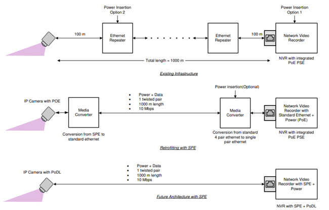
Classes 8 and 9 (48-V regulated power-sourcing equipment) or Classes 14 and 15 (50- to 58-V maximum) could support the required power levels for an IP camera, which might need as much as 52 W of power to operate. This power would be sufficient for most camera systems, even those with built-in heaters. For buildings that need upgrades, an intermediate solution would be to use standard Ethernet-to-SPE converters. Figure 3 provides examples of connectivity in an IP camera system.
 Figure 3 IP network camera
connectivity
Figure 3 IP network camera
connectivityFuture IP camera products are expected to support SPE, which will facilitate easier installations, as will network video recorders offering a power-sourcing equipment port. The move to better compressed video, over a simplified SPE network, enables better surveillance without an increase in complexity or cost.