SNVA381B November   2008  – December 2021 LM27341 , LM27341-Q1 , LM27342 , LM27342-Q1


  1.   Trademarks
  2. 1Introduction
  3. 2Evaluation Board Schematic
  4. 3Powering and Loading Considerations
    1. 3.1 Quick Start Procedure
    2. 3.2 Starting Up
    3. 3.3 Overcurrent Protection
    4. 3.4 Synchronization
    5. 3.5 Adjusting the Output Voltage
  5. 4Performance Characteristics
  6. 5Layout and Bill of Materials
  7. 6PCB Layout
  8. 7Revision History

Adjusting the Output Voltage

The output voltage is set using the following equation where R2 is connected between the FB pin and GND, and R1 is connected between VOUT and FB.

Equation 1. GUID-5B0F9059-2788-4DBB-9822-E123B59BF26E-low.png

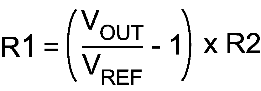
Adjusting the output voltage will affect the performance of the LM27342. In addition, output capacitors might not be rated for the new output voltage. Refer to the LM27342 data sheet for more information.