SNOAA69 April 2021 LM36922 , LM36923 , LM3697
3.2 How to Choose Key Components: Inductor and Capacitor, Schottky Diode D1
This section provides instructions for choosing key components:
- Power Capacitor: CIN, COUT
In general, all LM369xx power capacitor applications should be MLCC (Multiple Layer Ceramic Capacitor) because of smaller package and lower ESR, and lower power dissipation. The biggest shortage of MLCC is because the effective capacitance is derated due to DC biased voltage on the capacitor, when the DC biased voltage on MLCC increases, the effective capacitance of MLCC will decrease accordingly. It is necessary to keep enough capacitance, in actual design, the curve about DC biased voltage versus capacitance in MLCC data sheet is a useful tool to find suitable power capacitor. As Figure 3-2 shows, when DC biased voltage increases, effective capacitance will decrease quickly. Of course, the designer must consider whether the maximum voltage that power capacitor supports can meet the actual request, for example, if the power rail is 29 V, then the designer should choose 35-V MLCC to avoid any failure issues. Meanwhile the designer must consider the impact of temperature to effective capacitance, different ambient working temperatures will lead to the change of effective capacitance.
 Figure 3-2 MLCC Effective Capacitance vs DC Biased Voltage
and Temperature
Figure 3-2 MLCC Effective Capacitance vs DC Biased Voltage
and Temperature - Power Inductor: L
The power inductor is the key component to store energy. To the LM369xx family, a 10-µH inductor may work for most applications for a backlight driver. The designer must carefully calculate the peak current that flows through the power inductor to keep the inductor running in safe status. Use the formulas in Equation 5 to choose the correct power inductor. Additionally, pay attention to the curve of the effective inductance versus temperature and load current in the inductor data sheet. In general, when the load current is increased more than the saturation threshold that the inductor can handle, the effective inductance of the power inductor will decrease greatly, as Figure 3-3 shows. This leads to a destroyed inductor. Therefore, choose the correct inductor according to calculated IPEAK value and the curve of Figure 3-3 to avoid any saturation occurring. The inductor should be magnetic shielded to get better EMC performance at the system level.
Equation 5.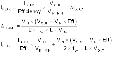
Where:
- Efficiency means the total efficiency of LM369xx, at worst case (such as the DCR of inductor is more than 100 mΩ), its minimum is 80%.
- fsw means switching frequency of converter: 1 MHz / 500KHz for Backlight Driver default as switching frequency.
- L is the target inductance of the power inductor, typical 10 µH with 1 MHz switch frequency.
- VOUT means the maximum output voltage of the converter.
For a simple method to calculate the backlight driver unit, assume the configuration of the LED string 3P7S (3 channel parallel with 7LED in series) and the forwarded voltage for each LED is 3.5 V, so the VOUT should be (7 + 1) × 3.5 V = 26 V. Figure 3-3 Inductance vs Load
Current
Figure 3-3 Inductance vs Load
Current
- Schottky Diode
A diode is used to rectify the output voltage on the backlight driver unit. In the discharge period of power inductor L, the diode is forward biased and outputs high voltage, while during the charging stage of L, this diode will be reverse-biased by VOUT. The maximum rating voltage that the diode can resist must be higher than target maximum VOUT. The type of diode should be Schottky for higher efficiency and good thermal performance in actual applications.