SNLA410 July 2022 DS280DF810
3 Temperature Optimization
When designing a system, it is important to consider the temperature range that the system may experience over the course of its operation. As it pertains to TI retimers, there are primarily two considerations that must be made. The first consideration is that the operating temperature of the device impacts the VCO of the CDR system. The second consideration is the impact of temperature on insertion loss.
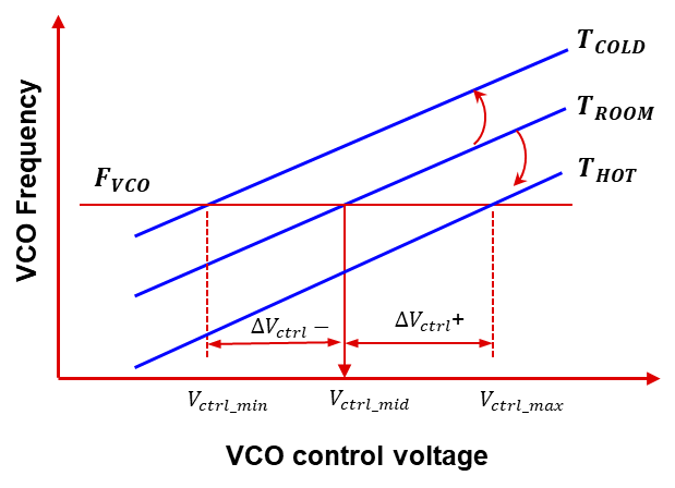
Different temperatures create an offset in the VCO frequency vs VCO control voltage curve, shown in Figure 3-1.
 Figure 3-1 Impact of
Temperature on VCO Frequency
Figure 3-1 Impact of
Temperature on VCO FrequencyBy varying device temperatures, it is possible to disrupt the CDR lock. Temperature lock range (TLR) is the operating temperature range for which the CDR can reliably maintain lock. This can often be found in the device-specific retimer’s data sheet. On TI’s 25 Gbps and 28 Gbps retimers, it is also possible to compensate for temperature. For more information, see DS2X0DF810 Junction Temperature Readback and Temperature Lock Range (TLR) Extension Procedures.
Insertion loss typically increases as temperature increases. The amount of variation depends on the transmission medium and transmission length. A variation in insertion loss during retimer operation can impact the ability of the retimer to re-transmit data without errors. This is due to the fact that RX compensation in the retimer is typically only adapted when initially establishing CDR lock. Without re-adapting, insertion loss variation may impact the BER of the system. TI’s 25 Gbps and 28 Gbps retimer families offer more flexibility in compensating for this than the 10 Gbps retimer family. In the 25 Gbps and 28 Gbps retimers, it is possible to enable continuous adaption of the DFE. This enables the retimer to adapt DFE while maintaining CDR lock. If DFE continuous adaption is enabled, the retimers are able to compensate for about ± 3dB of insertion loss variation. It may also be necessary to increase the tap weight of the 1st DFE tap since this tap is primarily responsible for compensating for insertion loss. Procedures for setting DFE continuous adaption and adjusting tap weights can be found in the programming guide for 25 Gbps and 28 Gbps retimers.
In general, TI’s 25 Gbps and 28 Gbps retimer family offers more flexibility in designing a system that will experience large temperature swings while operating.