SNAA355 April 2021 TPL1401
Design Notes
- The TPL1401 256-Tap, High-Accuracy, Digital Potentiometer With Buffered Wiper Data Sheet recommends using a 100-nF decoupling capacitor for the VDD pin, and a 1.5µF or greater bypass capacitor for the CAP pin. The CAP pin is connected to the internal LDO. Place these capacitors close to the device pins.
- When possible, use C0G (NPO) ceramic capacitors (C1) for input filtering. The dielectric used in these capacitors provides the most stable electrical properties over voltage, frequency, and temperature changes.
- Bias resistor, R1, will be decided based on the microphone (typical values range from 1kΩ to 10kΩ)
- The resistance of R2 and R4 will be chosen in such a way that there is enough headroom requirements for the TPL1401 to operate. The voltage at the output of the operational amplifier is used as the supply for the TPL1401. At any point, this voltage cannot go less than 1.8V (including the AC signal that is modulated on the DC bias ). For example, in this design, the target is 1Vrms, so a conservative commonmode voltage of 1.5V will be sufficient. With TPL1401 set to mid-code, the output of the operational amplifier will be 3V.
- TPL1401 should be used in VDD as reference mode of operation and set the initial code to mid code. In this configuration gain is inversely proportional to the CODE set in the TPL1401.
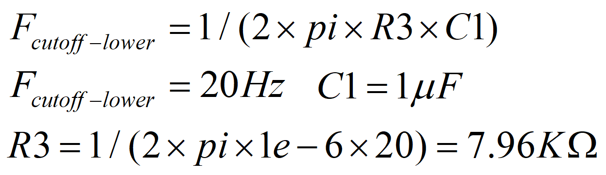
- Set the low frequency operation of the
circuit.
- Gain of the circuit is controlled by the
following equation:
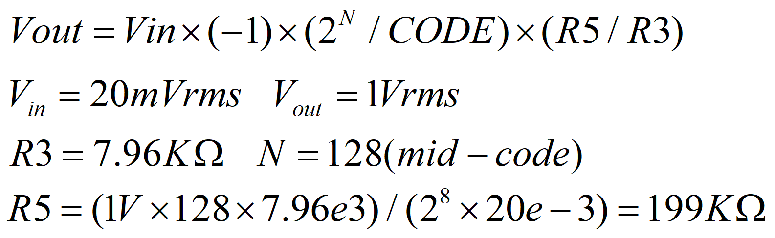
- Gain can be adjusted with DAC code. For DAC codes greater than 128, gain will decrease and for DAC codes less than 128, gain will increase. This way we can adjust the gain for tuning the sensitivity of the microphone.
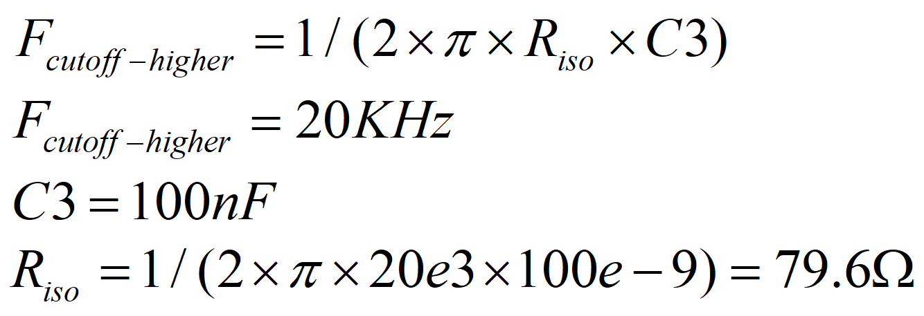
- Higher cutoff frequency will be set by Riso and
C3:
- The TPL1401 can be programmed with these initial register settings using I2C. The NVM of the device can be programmed using the PROTECT register to save all initial settings. After programming the NVM, the device will power load all registers with the values stored in the NVM.
- Choose an op amp with lower noise, low bias current and support operation of single supply down to 1.8V. The TLV906x family of devices can be a good choice.