SLVAF45 August 2021 TPS51397A , TPS566231 , TPS566235 , TPS566238 , TPS568230
3 Effects of Feedforward Capacitor on the Loop
 Figure 3-1 Scheme of Feedback Divider
Including Feedforward Capacitor
Figure 3-1 Scheme of Feedback Divider
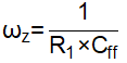
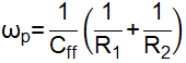
Including Feedforward CapacitorThe effects of adding feedforward capacitor in the feedback divider are studied in the application report [6]. A feedback divider including Cff is shown as Figure 3-1. Cff will introduce a pair of zero and pole in the converter loop. The angular frequency of the introduced zero and pole are:
The effects of the zero and pole introduced by Cff are shown as Figure 3-2.
Cff has both effects on the loop gain and phase. The loop gain is increased to boost bandwidth and optimize transient response. Also, the phase is boosted to increase the phase margin for system stability.
In application notes [2,8], some methods have been proposed to use Cff for phase margin enhancement. But in those methods, the bode plot results without Cff are always needed to get recommended Cff value. That feature makes those Cff selecting methods more applicable in the solution validation process but not in the application design process.
A new method to choose Cff is proposed in this application report. The bode plot results without Cff are not needed to get the recommended Cff value in this method, which makes it more applicable in application design.