SLVAEE9A October 2019 – July 2021 TPS2065C , TPS2065D , TPS2069C , TPS2069D , TPS25221
3.2 Validate the Influence of RC Filter to Normal Operation
In order to validate whether the method proposed has some impact on the IC’s normal operation, the delay time of added RC filter is verified. The following bench has been set up.
Vin = 5 V, slew rate is 5V/ms. With RC filter added, the parameters are R1 =1kΩ and C1 = 1 µF. RLoad = 2.5 Ω, current limit = 1.55A in TPS2065D. In theory, Fault_A from 3.3 V to 0.7 V, the time is 1.55 ms. In general, 0.7 V is regarded as low level of fault signal.
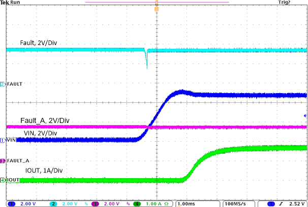
 Figure 3-4 Fault Signal Behavior as Vin Power up in Current Limit Condition
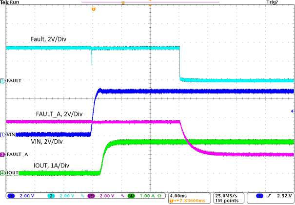
 Figure 3-5 Fault Signal Behavior as Current Limit
In Figure 3-4, as Vin ramps fast in the current limit condition, the Fault pin will glitch from 3.3 V to 1.4 V. However, the Fault_A that is connected to MCU almost has no glitch. Figure 3-5 indicates that in current limit condition, the Fault_A can also assert normally, but with a delay time about 1.55 ms. The results are in coincidence with theoretical calculation.