SLUUCO5A december 2022 – august 2023 BQ34Z100-R2
- 1
- Read This First
- 1 Introduction
-
2 Data Commands
- 2.1
Standard Data Commands
- 2.1.1
Control(): 0x00/0x01
- 2.1.1.1 CONTROL_STATUS: 0x0000
- 2.1.1.2 DEVICE TYPE: 0x0001
- 2.1.1.3 FW_VERSION: 0x0002
- 2.1.1.4 HW_VERSION: 0x0003
- 2.1.1.5 RESET_DATA: 0x0005
- 2.1.1.6 PREV_MACWRITE: 0x0007
- 2.1.1.7 CHEM ID: 0x0008
- 2.1.1.8 BOARD_OFFSET: 0x0009
- 2.1.1.9 CC_OFFSET: 0x000A
- 2.1.1.10 CC_OFFSET_SAVE: 0x000B
- 2.1.1.11 DF_VERSION: 0x000C
- 2.1.1.12 SET_FULLSLEEP: 0x0010
- 2.1.1.13 STATIC_CHEM_DF_CHKSUM: 0x0017
- 2.1.1.14 SEALED: 0x0020
- 2.1.1.15 IT ENABLE: 0x0021
- 2.1.1.16 CAL_ENABLE: 0x002D
- 2.1.1.17 RESET: 0x0041
- 2.1.1.18 EXIT_CAL: 0x0080
- 2.1.1.19 ENTER_CAL: 0x0081
- 2.1.1.20 OFFSET_CAL: 0x0082
- 2.1.2 StateOfCharge(): 0x02
- 2.1.3 MaxError(): 0x03
- 2.1.4 RemainingCapacity(): 0x04/0x05
- 2.1.5 FullChargeCapacity(): 0x06/07
- 2.1.6 Voltage(): 0x08/0x09
- 2.1.7 AverageCurrent(): 0x0A/0x0B
- 2.1.8 Temperature(): 0x0C/0x0D
- 2.1.9 Flags(): 0x0E/0x0F
- 2.1.10 FlagsB(): 0x12/0x13
- 2.1.11 Current(): 0x10/0x11
- 2.1.1
Control(): 0x00/0x01
- 2.2
Extended Data Commands
- 2.2.1 AverageTimeToEmpty(): 0x18/0x19
- 2.2.2 AverageTimeToFull(): 0x1A/0x1B
- 2.2.3 PassedCharge(): 0x1C/0x1D
- 2.2.4 DOD0Time(): 0x1E/0x1F
- 2.2.5 VoltScale(): 0x20
- 2.2.6 CurrScale(): 0x21
- 2.2.7 EnegyScale(): 0x22
- 2.2.8 AvailableEnergy(): 0x24/0x25
- 2.2.9 AveragePower(): 0x26/0x27
- 2.2.10 SerialNumber(): 0x28/0x29
- 2.2.11 InternalTemperature(): 0x2A/0x2B
- 2.2.12 CycleCount(): 0x2C/0x2D
- 2.2.13 StateOfHealth(): 0x2E/0x2F
- 2.2.14 ChargeVoltage(): 0x30/0x31
- 2.2.15 ChargeCurrent(): 0x32/0x33
- 2.2.16 PackConfiguration(): 0x3A/0x3B
- 2.2.17 DesignCapacity(): 0x3C/0x3D
- 2.2.18 DataFlashClass(): 0x3E
- 2.2.19 DataFlashBlock(): 0x3F
- 2.2.20 AuthenticateData/BlockData(): 0x40…0x53
- 2.2.21 AuthenticateChecksum/BlockData(): 0x54
- 2.2.22 BlockData(): 0x55…0x5F
- 2.2.23 BlockDataChecksum(): 0x60
- 2.2.24 BlockDataControl(): 0x61
- 2.2.25 GridNumber(): 0x62
- 2.2.26 LearnedStatus(): 0x63
- 2.2.27 Dod@Eoc(): 0x64/0x65
- 2.2.28 QStart(): 0x66/0x67
- 2.2.29 TrueRC(): 0x68/0x69
- 2.2.30 TrueFCC(): 0x6A/0x6B
- 2.2.31 StateTime(): 0x6C/0x6D
- 2.2.32 QmaxPassedQ(): 0x6E/0x6F
- 2.2.33 DOD0(): 0x70/0x71
- 2.2.34 QmaxDod0(): 0x72/0x73
- 2.2.35 QmaxTime(): 0x74/0x75
- 2.2.36 Data Flash Interface
- 2.1
Standard Data Commands
-
3 Fuel Gauging
- 3.1 Overview
- 3.2
Impedance Track Variables
- 3.2.1 Load Mode
- 3.2.2 Load Select
- 3.2.3 Reserve Cap-mAh
- 3.2.4 Reserve Cap-mWh/cWh
- 3.2.5 Energy Scale
- 3.2.6 Dsg Current Threshold
- 3.2.7 Chg Current Threshold
- 3.2.8 Quit Current, Dsg Relax Time, Chg Relax Time, and Quit Relax Time
- 3.2.9 Qmax
- 3.2.10 Update Status
- 3.2.11 Avg I Last Run
- 3.2.12 Avg P Last Run
- 3.2.13 Cell Delta Voltage
- 3.2.14 Ra Tables
- 3.2.15 StateOfCharge() Smoothing
- 3.2.16 Charge Efficiency
- 3.2.17 Lifetime Data Logging
- 3.3 Device Configuration
- 3.4 Voltage Measurement and Calibration
- 3.5 Temperature Measurement
- 3.6 Overtemperature Indication
- 3.7 Charging and Charge Termination Indication
- 3.8 The Scale Factors
- 3.9 LED Display
- 3.10 Alert Signal
- 3.11 Fast Resistance Scaling
- 4 Communications
- 5 Device Functional Modes
- 6 Power Control
- 7 Data Flash Summary
- 8 Gas Gauge Timing Considerations
- 9 HDQ Communication Basics
- 10Procedures to Seal and Unseal the Gauge
- 11Impedance Track Gauge Configuration
- 12Revision History
6.1 Reset Functions
When the device detects either a hardware or software reset (CE pin is driven low or the [RESET] bit of Control() is initiated, respectively), it determines the type of reset and increments the corresponding counter. This information is accessible by issuing the command Control() function with the RESET_DATA subcommand.
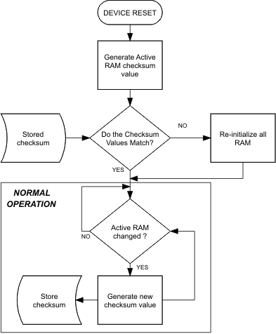
As shown in Figure 6-1, if a partial reset was detected, a RAM checksum is generated and compared against the previously stored checksum. If the checksum values do not match, the RAM is reinitialized (a “Full Reset”). The stored checksum is updated every time RAM is altered.
 Figure 6-1 Partial Reset Flow Diagram