SLUUCM6 August 2022
4.3 Load Transient Response
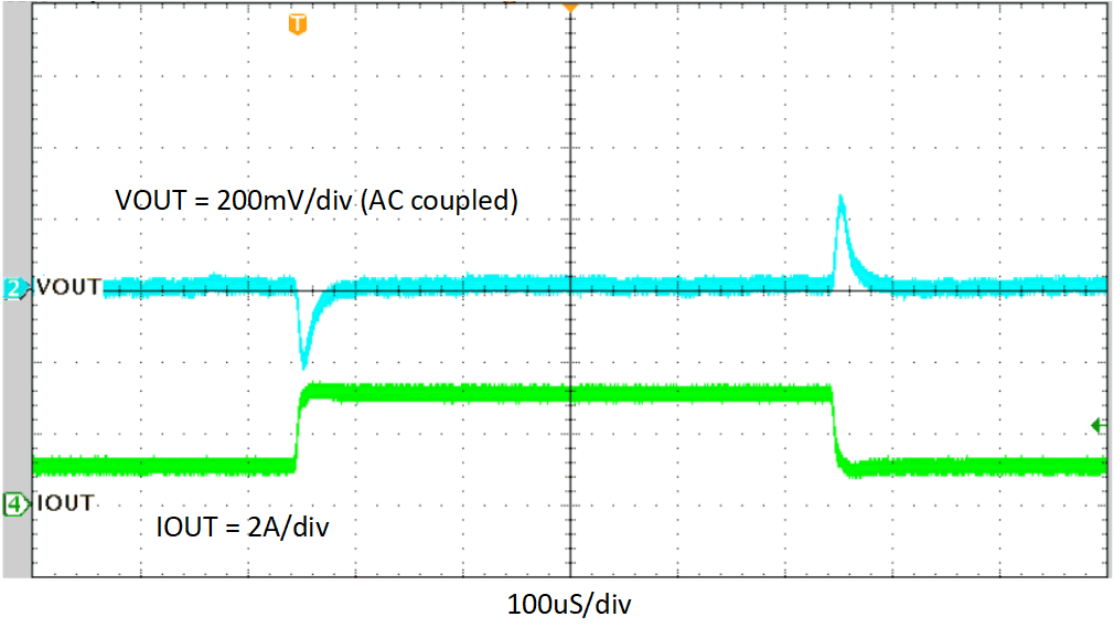
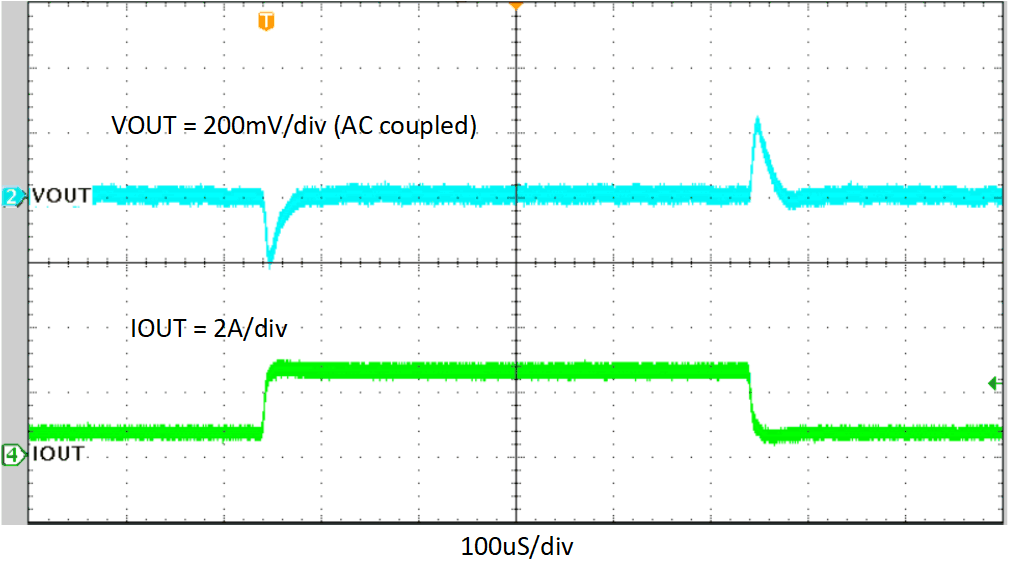
The TPS62933PEVM response to load transient is shown in Figure 4-2 and Figure 4-3. The current steps and slew rates are indicated in the figures with 20-MHz scope bandwidth. Total peak-to-peak voltage variation is as shown in the following figure.
 Figure 4-2 TPS62933PEVM Load
Transient Response, 1-A to 3-A Load Step, 0.8 A/µs
 Figure 4-3 TPS62933PEVM Load Transient Response, 0.5-A to 2.5-A Load Step, 0.8 A/µs