SLUU285D July 2007 – October 2021
- Trademarks
- 1Introduction
- 2TPS54383EVM Electrical Performance Specifications
-
3Schematic
- 3.1 Sequencing Jump (JP3)
- 3.2 Enable Jumpers (JP1 and JP2)
- 3.3
Test Point Descriptions
- 3.3.1 Input Voltage Monitoring (TP1 and TP2)
- 3.3.2 Channel 1 Output Voltage Monitoring (TP3 and TP4)
- 3.3.3 Channel 1 Loop Analysis (TP5, TP6, TP7 and TP8)
- 3.3.4 Channel 1 Switching Waveforms (TP9 and TP10)
- 3.3.5 TPS54383 Device Ground (TP11)
- 3.3.6 Channel 2 Switching Waveforms (TP12 and TP13)
- 3.3.7 Channel 2 Loop Analysis (TP14, TP15, TP16 and TP17)
- 3.3.8 Output Voltage Monitoring (TP18 and TP19)
- 4Test Set Up
- 5TPS54383EVM Typical Performance Data and Characteristic Curves
- 6EVM Assembly Drawings and Layout
- 7List of Materials
- 8Revision History
4.5 Control Loop Gain and Phase Measurement Procedure
- Connect 1 kHz to 1 MHz isolation transformer to TP6 and TP8 as show in Figure 4-3.
- Connect input signal amplitude measurement probe (Channel A) to TP8 as shown in Figure 4-3.
- Connect output signal amplitude measurement probe (Channel B) to TP6 as shown in Figure 4-3.
- Connect ground lead of Channel A and Channel B to TP5 & TP7 as shown in Figure 4-3.
- Inject 30 mV or less signal across R1 through isolation transformer.
- Sweep frequency from 1 kHz to 1 MHz with 10 Hz or lower post filter.
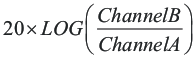
- Control loop gain can be measured by:
- Control loop phase is measured by the phase difference between Channel A and Channel B.
- Control loop for Channel 2 can be measured by making the following substitutions.
- Change TP6 to TP16
- Change TP8 to TP14
- Change TP5 to TP17
- Change TP7 to TP15
- Disconnect isolation transformer before making any other measurements (signal injection into feedback may interfere with accuracy of other measurements).