SLUAA12 March 2020 TPS53681
- Selection Considerations for Output Capacitors of Multiphase Voltage Regulators Part 1
3.2.2 Case 2: Large-signal Transient with Saturated Loop
In Case 2 (Figure 9), we assume that the control loop will go into partial or full saturation during transition period, the response of Isum will be limited by the controller itself and circuit parameters. During a heavy transient, the voltage loop saturates and demands pulses as fast as possible, which means only blanking time will be between each rising edge of PWM pulse. This feature is helpful to high repetitive transient response, for example in short duration of load transient, all phases turn-on would generate too much energy and cause big overshoot. "Over-compensation" can be avoided by adding blanking time.
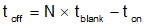
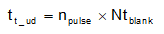
Blanking time prevents double pulsing of PWM, but at the same time limits the maximum capability of Isum rising. Based on this feature, minimum per-phase switching period Tsat is limited to N*tblank.
 Figure 9. Phase 1 Current IL1 in Case 2
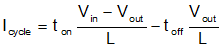
 Looking into current IL1 of phase 1 for example, shown in Figure 9. The effective switching cycle Tsat under saturation, and on/off time are calculated below:


The effective current rising Icycle in each phase, during one cycle is:
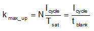
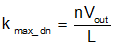
Isum is rising with efforts of all phase current, during full loop saturation, representing the maximum ability of Isum rising, this slew rate is:
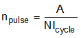
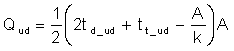
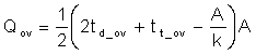
Loop delay time will become critical for undershoot and overshoot when loop is saturated. It means how much time needed for Isum to respond to rising or falling Io. This delay time is defined as td_ud and td_ov here, and affected by loop dynamic response, but typically 3 to 5 extra pulses if loop compensation is designed appropriately. Assume nex is number of extra pulses, we use td_ud/td_ov=nex*ton to estimate roughly.
 Figure 10. Undershoot and Overshoot Calculation in Case 2
 Figure 10 shows waveforms of how current difference contributes to undershoot and overshoot. With knowing Icycle each cycle when current is rising, we can easily know how many cycles and also time duration, to make Isum and Io equal.
The discharges and undershoot are as follows:

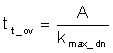
When Isum is falling during full loop saturation, there is no pulse until steady state. Similarly, we have the following equations:

From formulas above, reducing inductance can surly lower undershoot/overshoot under saturated loop, but at the expense of efficiency with more current ripple. Also, when the loop is fully saturated, the output capacitance required will be affected by almost all the variations of load step characteristics, loop delay time, controller settings, and component parameters.