SLLA593 August 2022 TUSB211 , TUSB212 , TUSB216 , TUSB216I , TUSB217A
2 Host Mode Testing
When performing high-speed signal quality testing in the host mode, no enumeration or handshaking is required, but it is crucial that the system is setup in the correct way for the TUSB21XX device to detect and enable high-speed signal conditioning.
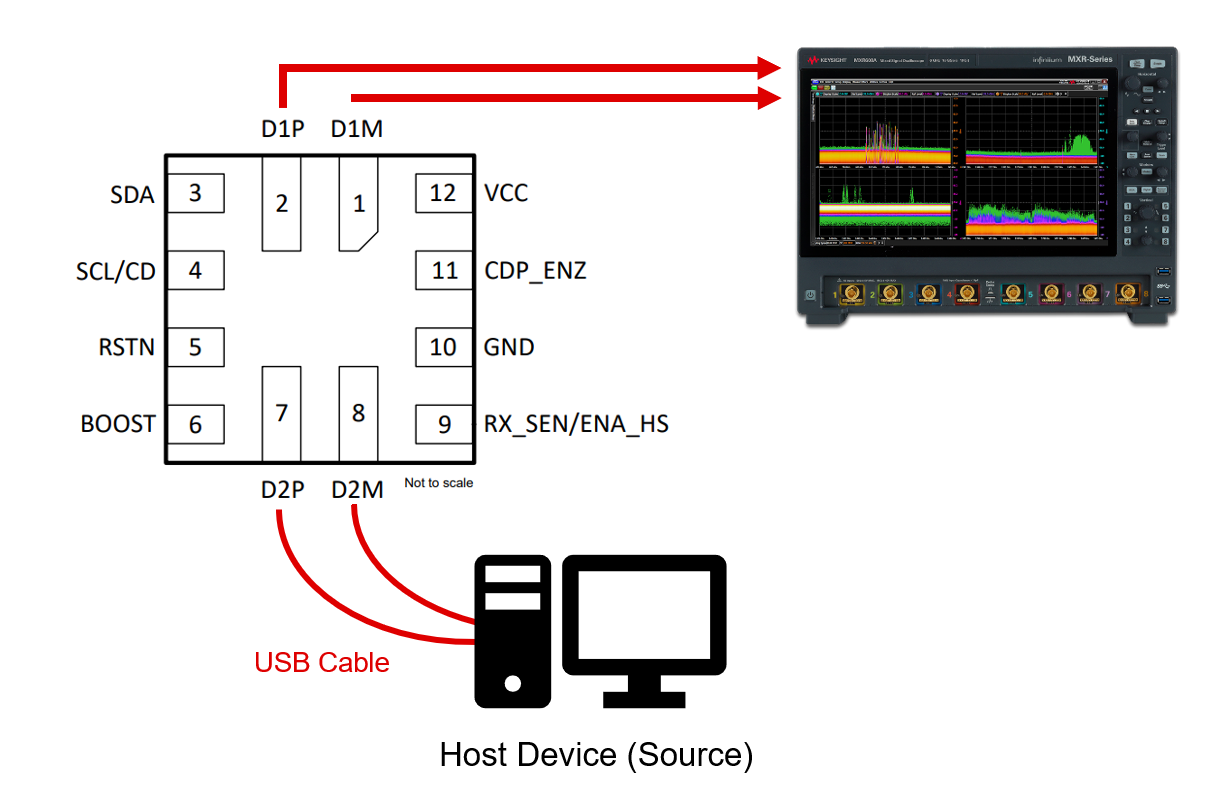
A generalized system diagram for host mode testing is shown in Figure 2-1. The host device (a PC in this case) is connected to the input of the TUSB21XX device via a USB cable. The host must be a Windows device able to install and run the USB-IF HSET software. In cases where this is not possible, embedded host mode testing is required (Section 4). The output of the TUSB21XX is connected directly to an oscilloscope for test packet measurement. Practically, the output will likely be interfaced with the TUSB21XX through a USB receptacle. In this case, a test fixture is needed to break out the D1P/D1M data lines to the oscilloscope input.
 Figure 2-1 Host Mode Test Setup