SLLA500 December 2020 TUSB2E22
1 Introduction to the Embedded USB2 (eUSB2) Physical Layer Supplement
The embedded USB2 (eUSB2) Physical Layer Supplement to the USB 2.0 Specification was created to address the need for a low voltage, power efficient USB 2.0 Phy solution. It eliminates the need for 3.3-V IO signaling in small process technologies. eUSB2 is capable of supporting USB high-speed, full-speed, and low-speed operation, as well as the USB 2.0 L1/L2 link power management requirements. In addition, eUSB2 requires no change to the existing USB 2.0 software programming model. eUSB2 applications can be implemented in native mode or repeater mode as described below. This document focus on eUSB2 applications that use repeater mode.
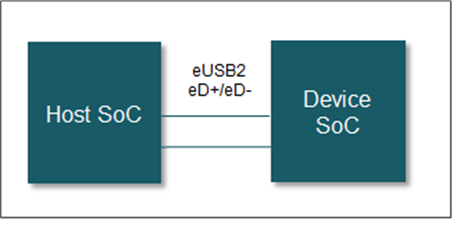
- Native mode is used for permanent chip-to-chip communications with direct eUSB2 signal connections which can support long trace lengths. Standard USB 2.0 hosts or devices cannot directly connect to a native eUSB2 application.
 Figure 1-1 eUSB2 Native
Mode Use Case
Figure 1-1 eUSB2 Native
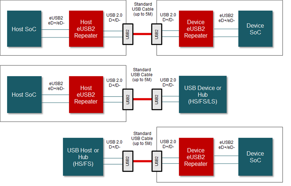
Mode Use Case- Repeater mode enables chips implementing eUSB2 to connect to standard USB hosts or devices through a separate eUSB2 repeater. An eUSB2 repeater can also be routed to external connectors for complete traditional USB 2.0 interoperability.
 Figure 1-2 eUSB2 Repeater
Mode Use Cases