SLAZ094AB October 2012 – May 2021 CC430F5137
- 1Functional Advisories
- 2Preprogrammed Software Advisories
- 3Debug Only Advisories
- 4Fixed by Compiler Advisories
- 5Nomenclature, Package Symbolization, and Revision Identification
-
6Advisory Descriptions
- 6.1 ADC24
- 6.2 ADC25
- 6.3 ADC27
- 6.4 ADC29
- 6.5 ADC42
- 6.6 ADC69
- 6.7 AES1
- 6.8 BSL7
- 6.9 COMP4
- 6.10 COMP10
- 6.11 CPU18
- 6.12 CPU20
- 6.13 CPU21
- 6.14 CPU22
- 6.15 CPU23
- 6.16 CPU24
- 6.17 CPU25
- 6.18 CPU26
- 6.19 CPU27
- 6.20 CPU28
- 6.21 CPU29
- 6.22 CPU30
- 6.23 CPU31
- 6.24 CPU32
- 6.25 CPU33
- 6.26 CPU34
- 6.27 CPU35
- 6.28 CPU39
- 6.29 CPU40
- 6.30 CPU46
- 6.31 CPU47
- 6.32 DMA4
- 6.33 DMA7
- 6.34 DMA8
- 6.35 DMA10
- 6.36 EEM8
- 6.37 EEM9
- 6.38 EEM11
- 6.39 EEM13
- 6.40 EEM14
- 6.41 EEM16
- 6.42 EEM17
- 6.43 EEM19
- 6.44 EEM23
- 6.45 FLASH29
- 6.46 FLASH31
- 6.47 FLASH37
- 6.48 JTAG20
- 6.49 JTAG26
- 6.50 JTAG27
- 6.51 MPY1
- 6.52 PMAP1
- 6.53 PMM8
- 6.54 PMM9
- 6.55 PMM10
- 6.56 PMM11
- 6.57 PMM12
- 6.58 PMM14
- 6.59 PMM15
- 6.60 PMM17
- 6.61 PMM18
- 6.62 PMM20
- 6.63 PORT15
- 6.64 PORT16
- 6.65 PORT17
- 6.66 PORT19
- 6.67 PORT21
- 6.68 RF1A1
- 6.69 RF1A2
- 6.70 RF1A3
- 6.71 RF1A5
- 6.72 RF1A6
- 6.73 RF1A8
- 6.74 RTC3
- 6.75 RTC6
- 6.76 SYS16
- 6.77 TAB23
- 6.78 UCS6
- 6.79 UCS7
- 6.80 UCS9
- 6.81 UCS10
- 6.82 UCS11
- 6.83 USCI26
- 6.84 USCI30
- 6.85 USCI31
- 6.86 USCI34
- 6.87 USCI35
- 6.88 USCI39
- 6.89 USCI40
- 6.90 WDG4
- 7Revision History
6.59 PMM15
PMM Module
Category
Functional
Function
Device may not wake up from LPM2, LPM3, or LPM4
Description
Device may not wake up from LPM2, LPM3 or LMP4 if an interrupt occurs within 1 us after the entry to the specified LPMx; entry can be caused either by user code or automatically (for example, after a previous ISR is completed). Device can be recovered with an external reset or a power cycle. Additionally, a PUC can also be used to reset the failing condition and bring the device back to normal operation (for example, a PUC caused by the WDT).
This effect is seen when:
- A write to the SVSMHCTL and SVSMLCTL registers is immediately followed by an LPM2, LPM3, LPM4 entry without waiting the requisite settling time ((PMMIFG.SVSMLDLYIFG = 0 and PMMIFG.SVSMHDLYIFG = 0)).
or
The following two conditions are met:
- The SVSL module is configured for a fast wake-up or when the SVSL/SVML module is turned off. The affected SVSMLCTL register settings are shaded in the following table.
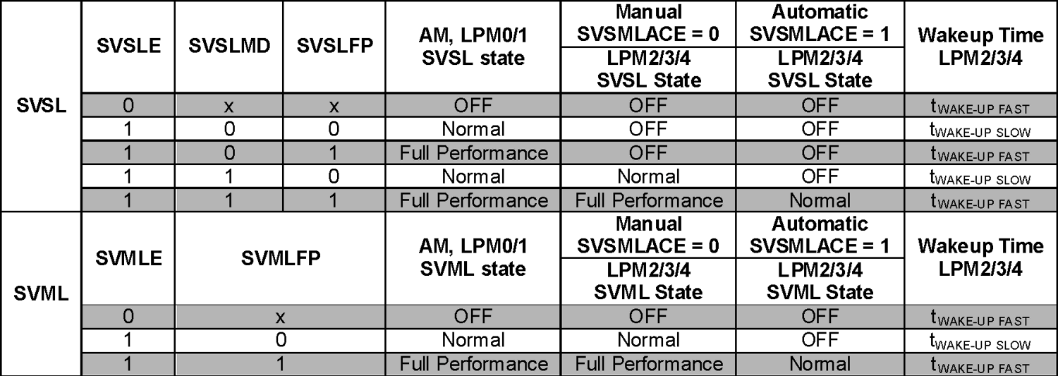
and
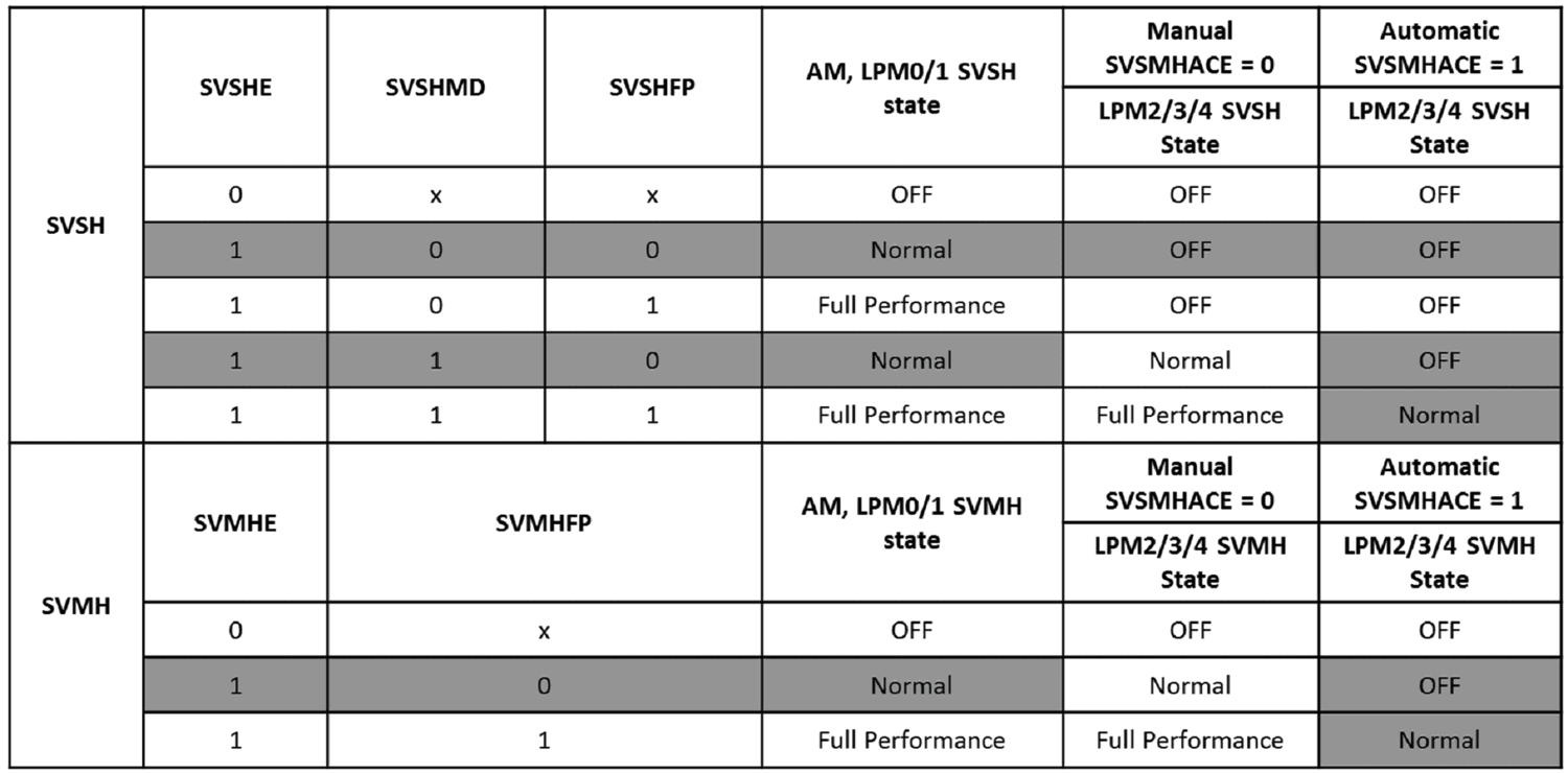
-The SVSH/SVMH module is configured to transition from Normal mode to an OFF state when moving from Active/LPM0/LPM1 into LPM2/LPM3/LPM4 modes. The affected SVSMHCTL register settings are shaded in the following table.
Workaround
Any write to the SVSMxCTL register must be followed by a settling delay (PMMIFG.SVSMLDLYIFG = 0 and PMMIFG.SVSMHDLYIFG = 0) before entering LPM2, LPM3, LPM4.
and
1. Ensure the SVSx, SVMx are configured to prevent the issue from occurring by the following:
- Configure the SVSL module for slow wake up (SVSLFP = 0). Note that this will increase the wakeup time from LPM2/3/4 to twakeupslow (~150 us).
or
- Do not configure the SVSH/SVMH such that the modules transition from Normal mode to an OFF state on LPM entry and ensure SVSH/SVMH is in manual mode. Instead force the modules to remain ON even in LPMx. Note that this will cause increased power consumption when in LPMx.
Refer to the MSP430 Driver Library(MSPDRIVERLIB) for proper PMM configuration functions.
Use the following function, PMM15Check (void), to determine whether or not the existing PMM configuration is affected by the erratum. The return value of the function is 1 if the configuration is affected, and 0 if the configuration is not affected.
unsigned char PMM15Check (void)
{
// First check if SVSL/SVML is configured for fast wake-up
if ( (!(SVSMLCTL & SVSLE)) || ((SVSMLCTL & SVSLE) && (SVSMLCTL & SVSLFP)) ||
(!(SVSMLCTL & SVMLE)) || ((SVSMLCTL & SVMLE) && (SVSMLCTL & SVMLFP)) )
{ // Next Check SVSH/SVMH settings to see if settings are affected by PMM15
if ((SVSMHCTL & SVSHE) && (!(SVSMHCTL & SVSHFP)))
{
if ( (!(SVSMHCTL & SVSHMD)) || ((SVSMHCTL & SVSHMD) &&
(SVSMHCTL & SVSMHACE)) )
return 1; // SVSH affected configurations
}
if ((SVSMHCTL & SVMHE) && (!(SVSMHCTL & SVMHFP)) && (SVSMHCTL & SVSMHACE))
return 1; // SVMH affected configurations
}
return 0; // SVS/M settings not affected by PMM15
}
}
2. If fast servicing of interrupts is required, add a 150us delay either in the interrupt service routine or before entry into LPM3/LPM4.