SLAAE63 August 2022 MSP430FR2353 , MSP430FR2353 , MSP430FR2355 , MSP430FR2355
2 Hardware Implementation
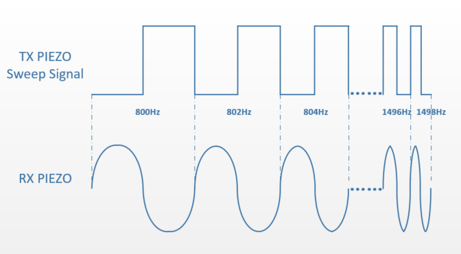
The sensor uses two piezoelectric actuators, one to drive the tuning fork (TX) and the other to receive the response of the fork (RX). An MCU timer module is used to produce a 50:50 duty cycle frequency sweep driving the TX. To measure higher-viscousity liquids, the sweep frequency range is set from 800 Hz to 1498 Hz with the increment of 2 Hz after each period, which results in (1498 Hz – 800 Hz) / 2 Hz = 350 periods per sweep (approximately 600-ms duration). Figure 2-1 shows the TX sweep signal and the expected RX response signal.
 Figure 2-1 TX Piezo Sweep Signal and RX Piezo Response Signal
Waveform
Figure 2-1 TX Piezo Sweep Signal and RX Piezo Response Signal
WaveformThe resonant frequency of the tested tuning fork in air is approximately 1368 Hz, which is determined by type of fork level sensor. Each different type of tuning fork level sensor has a different resonant frequency, so the user must adjust the example sweep signal range accordingly. The MCU timer is set for running at 8-MHz frequency. The discrete steps of the timer for the sweep signal generation introduce a maximum error of ±0.13 Hz for a given frequency. Two MCU output pins are used for the PWM signal for better drive capability of the TX sweep signal. Optionally, the user can add external buffers or switches to add even more driving capability of the sweep signal.
Figure 2-2 shows the block diagram. In a tuning fork level sensor switch application, the power is typically from 4-20mA loop, so an additional LDO is needed. This example application uses a high-voltage input LDO (30 V), the TLV76033, to power the MCU. Because the MSP430FR2355 integrates an SVS function, no external voltage monitor IC is needed.
For signal conditioning, three SAC modules are used to offset, filter, and amplify the response signal of the RX piezo. The RX piezo itself is referenced by a positive voltage to avoid negative input voltages at the MCU pins. The biasing voltage is generated by SAC1, which is configured in DAC buffer mode. The user can adjust the DC bias voltage through the MCU internal DAC function for different tuning fork level sensor types. In this example, , 500 mVDC is chosen.
SAC2 is configured as noninverting PGA with fixed gain to use the analog input range of the ADC of 0 to 2.5 V with the RX piezo in air, which typically has the highest amplitude. In this way, MCU internal ADC can maximize the sample accuracy. And another benefit of the noninverting amplifier configuration is the high input impedance required for the RX piezo. In this scenario, 2-V/V amplify gain is chosen. Additionally, an external low-pass filter (R-C) is implemented to limit the bandwidth of the input signal. The corner frequency is based on the natural resonant frequency in the air of the tuning fork level sensor. In this scenario, the natural resonant frequency is 1368 Hz, so a low-pass filter (R = 10 kΩ, C = 10 nF) is chosen based on Equation 1.
SAC3 is also configured as noninverting PGA to add gain to the amplitude of the RX signal for higher viscosity liquids. Typically, higher-viscosity liquids have lower resonant amplitudes, which can be hard to measure by the MCU ADC. The user can adjust the gain of SAC3 corresponding. In this scenario, 1 V/V is chosen. In addition, a 3-MΩ resistor is recommended in parallel to the RX piezo to decrease the output impedance.
The ADC converter sample point is dependent on the TX driving signal. Tests have shown that the maximum RX signal amplitude happens at the resonance frequency, which has fixed phase shift of 80 degrees if the tuning fork is in liquid instead of air. This shift is independent of the viscosity of the liquid. Therefore, the RX signal can be sampled once per TX period with an 80-degree shift to the TX signal to decrease the amount of data to be processed. Because the peak of the RX amplitude is at a different phase compared to out-of-resonance air frequencies, the selectivity of the resonance frequency is further enhanced. The software can detect if the tuning fork level sensor is immersed in the target viscous liquid, therefore outputting a switch signal indicating the liquid level is achieved.