SLAA897 June 2019 MSP430FR2353 , MSP430FR2355
2.1 Using SAC to Generate the LED Drive
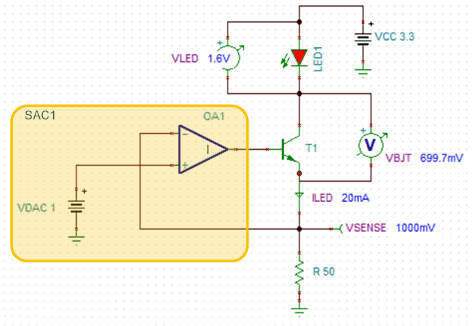
Many pulse oximeter designs use back-to-back connected Red and IR LEDs which need four transistors for driving. The transistors are connected in H-bridge fashion to drive one LED at a time. To eliminate two transistors, the LED can be driven using single transistor as shown in Figure 3. The SAC can be configured as DAC output configuration (the internal register settings should be PSEL=01, NSEL=00, MSEL=xx).
 Figure 3. Simulation of the LED Drive Circuitry
 In the SAC1, DAC1 voltage can be set to VDAC and is connected to non-inverting terminal of OA1. Due to virtual ground, the inverting terminal will also lock to the same voltage (VDAC) and the output of the OA1 varies in order to keep the inverting and non-inverting OA1 terminals at the same potential (VDAC). This potential gets reflected across the sense resistor R which sets the current flowing through the LED. The current through the LED is calculated as:

Also, a VCC value should be chosen such that it can sustain the voltage drops across the LED, the transistor and the sense resistor.

Where,
VLED = 2.1 V to 2.8 V for Red LED & 1.3 V to 1.8 V for IR LED
VSENSE= VDAC (programmable) from 0 V to 2.5 V