SLAA235A February 2005 – August 2018 MSP430F147 , MSP430F147 , MSP430F148 , MSP430F148 , MSP430F149 , MSP430F149
2 Hardware Description
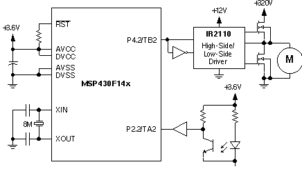
An MSP430F149 device is used in this motor control application. You can substitute by any other MSP430 MCU with both Timer_A and Timer_B. Figure 6 shows the application block schematic. The MSP430 MCU is sourced by an 8-MHz crystal to provide a high-resolution clock source that is used for both PWM generation and speed measurement.
The universal serial motor is driven with a PWM signal that is generated using a Timer_B capture/compare block operated in compare mode. The MCU output signal is then delivered to the actual motor driver output stage. In this application demo, this driver stage is supplied by the rectified 230‑V mains voltage.
To provide feedback for the fuzzy logic control loop, an optical sensor is used. This sensor consists of a light transmitter and a receiver. Using a slotted disc that is attached to the motor shaft, 24 impulses for each motor revolution are generated. The actual motor speed is obtained by measuring the time between two successive impulses with a Timer_A capture/compare block operated in capture mode. An 8-tap moving average filter is used to minimize the measurement error that occurs with higher motor speeds.
 Figure 6. Hardware Block Schematic