SBVA092 June 2022 TPS7A14
3.2 Transient Response in Time Domain
Figure 3-3 shows that added CFF can improve the load transient performance. The amount of ripple tells the improvement. Test condition has a transient of 10 mA to 1.0 A and A/us slew rate. It can be left for further tune by users.
 Figure 3-3 Load Transient Performance Comparison
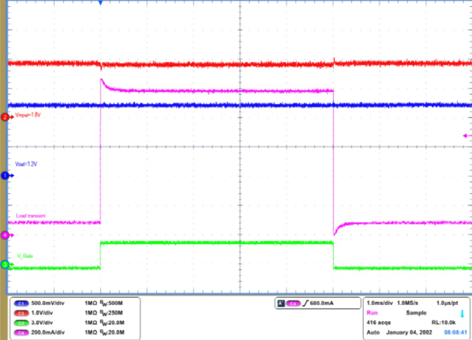
 Figure 3-4 Transient Response of Modified Vout=1.2 V (with
10 nF Cff)