SLVS059T June 1976 – January 2015
PRODUCTION DATA.
- 1 Features
- 2 Applications
- 3 Description
- 4 Simplified Schematic
- 5 Revision History
- 6 Pin Configuration and Functions
-
7 Specifications
- 7.1 Absolute Maximum Ratings
- 7.2 ESD Ratings
- 7.3 Recommended Operating Conditions
- 7.4 Thermal Information
- 7.5 Electrical Characteristics — uA78M33C
- 7.6 Electrical Characteristics — uA78M33I
- 7.7 Electrical Characteristics — uA78M05C
- 7.8 Electrical Characteristics — uA78M05I
- 7.9 Electrical Characteristics — uA78M06C
- 7.10 Electrical Characteristics — uA78M08C
- 7.11 Electrical Characteristics — uA78M09C
- 7.12 Electrical Characteristics — uA78M10C
- 7.13 Electrical Characteristics — uA78M12C
- 7.14 Typical Characteristics
- 8 Detailed Description
- 9 Application and Implementation
- 10Power Supply Recommendations
- 11Layout
- 12Device and Documentation Support
- 13Mechanical, Packaging, and Orderable Information
封装选项
请参考 PDF 数据表获取器件具体的封装图。
机械数据 (封装 | 引脚)
- KVU|3
- DCY|4
- KCS|3
散热焊盘机械数据 (封装 | 引脚)
订购信息
9 Application and Implementation
NOTE
Information in the following applications sections is not part of the TI component specification, and TI does not warrant its accuracy or completeness. TI’s customers are responsible for determining suitability of components for their purposes. Customers should validate and test their design implementation to confirm system functionality.
9.1 Application Information
The UA78Mxx devices are ideal for use as linear regulators with few external components needed for a working design. They are also useful for attenuating power supply noise.
9.2 Typical Application
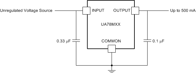
 Figure 2. Fixed-Output Regulator
9.2.1 Design Requirements
An 0.33-µF decoupling capacitor on the input and a 0.1-µF decoupling capacitor on the output are recommended for the UA78Mxx to behave as close to datasheet specifications as possible.
9.2.2 Detailed Design Procedure
The customer's end application will determine how the schematic for UA78Mxx is designed. For example, if there is a load connected to a negative voltage as its ground, a clamp diode may be necessary on the output. In the event of an input short circuit or another case where the output voltage can be higher than the input, a diode shunt can be connected across the device with the anode at the output and cathode at the input
9.2.3 Application Curves
 Figure 3. V_OUTPUT vs V_INPUT for
IOUTPUT = 5 mA and 500 mA (25°C)