SLVS432F September   2002  – June 2015 TPS62050 , TPS62051 , TPS62052 , TPS62054 , TPS62056

PRODUCTION DATA.  

  1. Features
  2. Applications
  3. Description
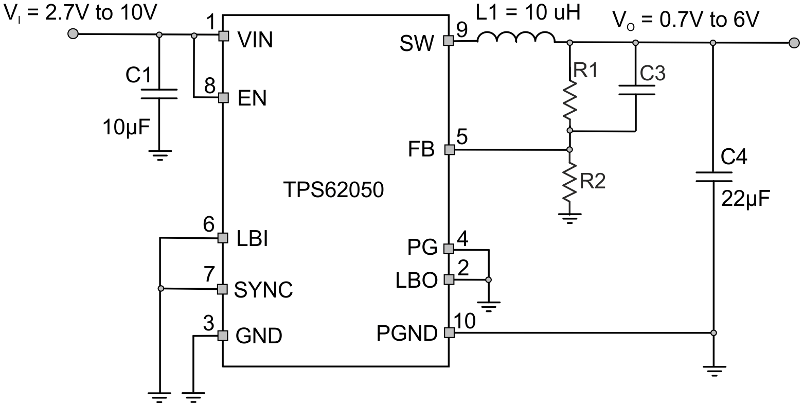
  4. Typical Application Schematic
  5. Revision History
  6. Device Comparison Table
  7. Pin Configuration and Functions
  8. Specifications
    1. 8.1 Absolute Maximum Ratings
    2. 8.2 ESD Ratings
    3. 8.3 Recommended Operating Conditions
    4. 8.4 Thermal Information
    5. 8.5 Electrical Characteristics
    6. 8.6 Typical Characteristics
  9. Detailed Description
    1. 9.1 Overview
    2. 9.2 Functional Block Diagram
    3. 9.3 Feature Description
      1. 9.3.1 Enable and Overtemperature Protection
      2. 9.3.2 Low-Battery Detector (Standard Version)
      3. 9.3.3 ENABLE / Low-Battery Detector (Enhanced Version) TPS62051 Only
      4. 9.3.4 Undervoltage Lockout
      5. 9.3.5 Power Good Comparator
      6. 9.3.6 Synchronization
    4. 9.4 Device Functional Modes
      1. 9.4.1 Soft-Start
      2. 9.4.2 Constant Frequency Mode Operation (SYNC = HIGH)
      3. 9.4.3 Power-Save Mode Operation (SYNC = LOW)
      4. 9.4.4 100% Duty Cycle Low Dropout Operation
      5. 9.4.5 No Load Operation
  10. 10Application and Implementation
    1. 10.1 Application Information
    2. 10.2 Typical Applications
      1. 10.2.1 Standard Circuit for Adjustable Version
        1. 10.2.1.1 Design Requirements
        2. 10.2.1.2 Detailed Design Procedure
          1. 10.2.1.2.1 Inductor Selection
          2. 10.2.1.2.2 Output Capacitor Selection
          3. 10.2.1.2.3 Input Capacitor Selection
          4. 10.2.1.2.4 Feedforward Capacitor
        3. 10.2.1.3 Application Curves
      2. 10.2.2 Standard Circuit for Fixed Voltage Version
        1. 10.2.2.1 Design Requirements
        2. 10.2.2.2 Detailed Design Procedure
        3. 10.2.2.3 Application Curves
    3. 10.3 System Examples
  11. 11Power Supply Recommendations
  12. 12Layout
    1. 12.1 Layout Guidelines
    2. 12.2 Layout Example
  13. 13Device and Documentation Support
    1. 13.1 Device Support
      1. 13.1.1 Third-Party Products Disclaimer
    2. 13.2 Related Links
    3. 13.3 Community Resource
    4. 13.4 Trademarks
    5. 13.5 Electrostatic Discharge Caution
    6. 13.6 Glossary
  14. 14Mechanical, Packaging, and Orderable Information

封装选项

请参考 PDF 数据表获取器件具体的封装图。

机械数据 (封装 | 引脚)
  • DGS|10
散热焊盘机械数据 (封装 | 引脚)
订购信息

12 Layout

12.1 Layout Guidelines

All capacitors must be soldered as close as possible to the IC.

For information on the PCB layout, see the user's guide, SLVU081.

Keep the feedback track as short as possible. Any coupling to the FB pin may cause additional output voltage ripple. The feedback connection from the output capacitor C4 to R1 of the feedback network is made directly from the pad of C4 as shown by the via. The connection of GND with PGND is done similarly directly at the PGND pad of C4. Uncritical signals like the connections for LBI, LBO, and PG are not shown for better readability.

12.2 Layout Example
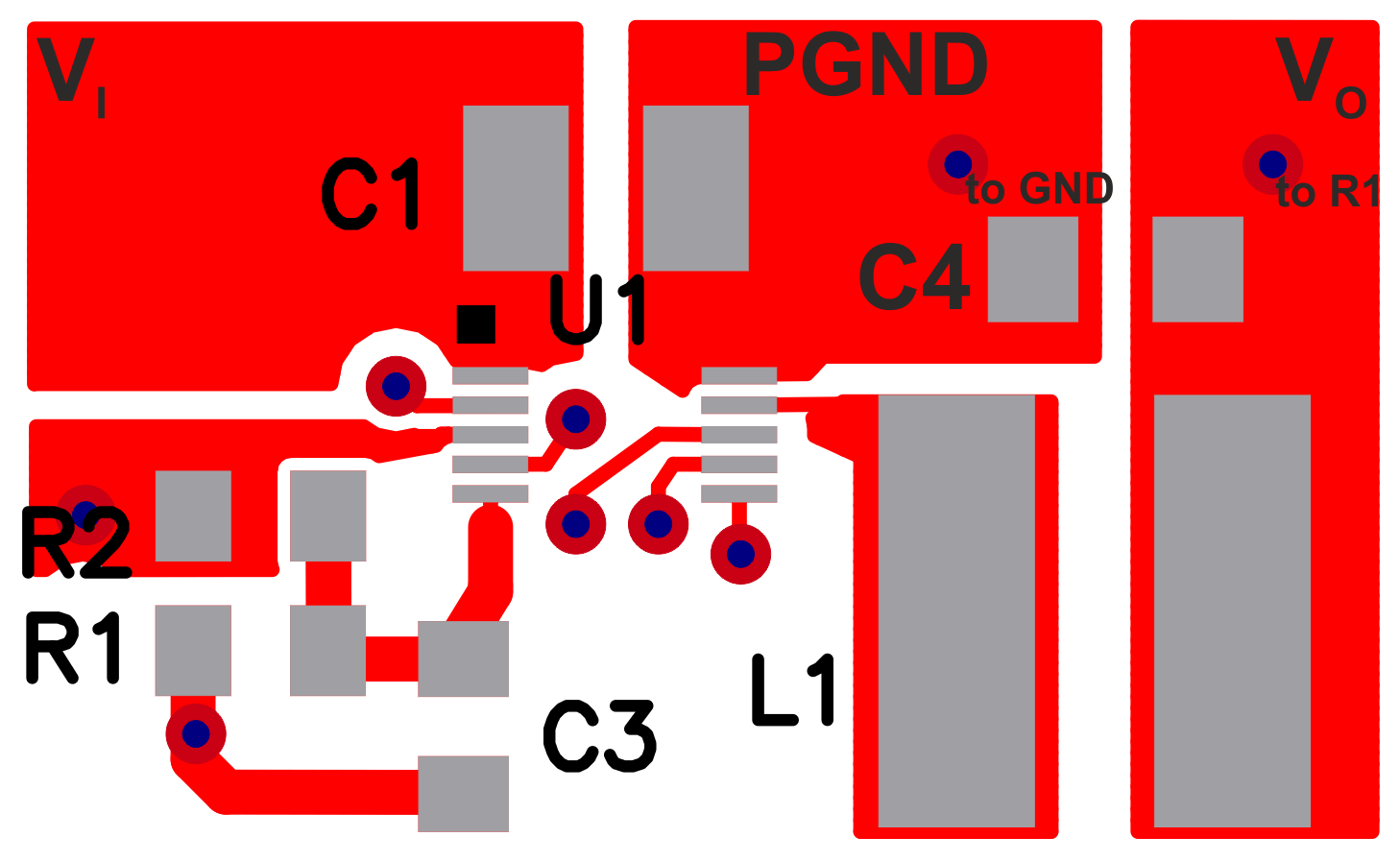
TPS62050 TPS62051 TPS62052 TPS62054 TPS62056 TPS62050_layout.gifFigure 24. Layout
TPS62050 TPS62051 TPS62052 TPS62054 TPS62056 TPS62050_schematics_adjustable.gifFigure 25. Associated Layout Schematic