ZHCSDK1 March 2015 TPS61196-Q1
PRODUCTION DATA.
- 1 特性
- 2 应用范围
- 3 说明
- 4 修订历史记录
- 5 Pin Configuration and Functions
- 6 Specifications
-
7 Detailed Description
- 7.1 Overview
- 7.2 Functional Block Diagram
- 7.3 Feature Description
- 7.4
Device Functional Modes
- 7.4.1
Protections
- 7.4.1.1 Switch Current Limit Protection Using the ISNS Pin
- 7.4.1.2 LED Open Protection
- 7.4.1.3 LED Short-Cross Protection Using the FBP Pin
- 7.4.1.4 Schottky Diode Open Protection
- 7.4.1.5 Schottky Diode Short Protection
- 7.4.1.6 IFB Overvoltage Protection During Start-up
- 7.4.1.7 Output Overvoltage Protection Using the OVP Pin
- 7.4.1.8 Output Short-to-Ground Protection
- 7.4.1.9 IFB Short-to-Ground Protection
- 7.4.1.10 ISET Short-to-Ground Protection
- 7.4.1.11 Thermal Protection
- 7.4.2 Indication For Fault Conditions
- 7.4.1
Protections
- 8 Application and Implementation
- 9 Power Supply Recommendations
- 10Layout
- 11器件和文档支持
- 12机械封装和可订购信息
1 特性
- 8V 至 30V 输入电压
- 高达 120V 输出电压
- 100kHz 至 800kHz 可编程开关频率
- 为 LED 提供电压的自适应升压输出
- 六路灌电流、200mA 连续输出、400mA 脉冲输出(每个灯串)
- 灯串之间 ±1.5% 的电流匹配
- 分辨率高达 5000:1 的高精度 PWM 亮度调节
- 可编程过压保护 (OVP) 阈值
- 可编程输入欠压闭锁 (UVLO) 阈值
- 可调软启动时间
- 内置 LED 开路和短路保护
- 内置肖特基二极管开路和短路保护
- 内置 ISET 短路保护
- 内置 IFB 短路保护
- 热关断
2 应用范围
- 汽车 LCD 背光
- 汽车仪表板显示器
- 汽车辅助显示器
3 说明
TPS61196-Q1 可为汽车 LCD 背光照明应用提供高度集成的解决方案,可使每个灯串都具有独立的 PWM 调光功能。 该器件是一款电流模式升压控制器,能够驱动多达六个由多个 LED 串联组成的白色发光二极管 (WLED) 灯串。 每个灯串均具有独立的电流稳压器,稳压器可在 50mA 至 400mA 范围内调节 LED 电流(匹配精度 ±1.5%)。 可在 0.3V 至 1V 范围内编程最低灌电流电压,以符合不同的 LED 电流设置。 器件的输入电压范围为 8V 至 30V。
TPS61196-Q1 会自动调整升压控制器的输出电压,以提供具有最大正向压降的 LED 灯串所需要的电压以及该灯串 IFB 引脚上所需的最小电压,从而优化驱动器效率。 可通过外部电阻将其开关频率设定在 100kHz 至 800kHz 之间。
TPS61196-Q1 支持直接 PWM 调光。 每个灯串均具有独立的 PWM 控制输入。 在 PWM 调光模式下,将通过外部 PWM 信号决定导通或关断 LED 电流的频率和占空比。 PWM 频率范围为 90kHz 至 22kHz。
TPS61196-Q1 集成了过流保护、输出短路保护、ISET 接地短路保护、二极管开路和短路保护、LED 开路和短路保护以及过热关断电路。 此外,TPS61196-Q1 还可检测 IFB 引脚接地短路以保护 LED 灯串。 该器件还具有可编程的输入欠压闭锁阈值和输出过压保护阈值。
器件信息(1)
| 器件型号 | 封装 | 封装尺寸(标称值) |
|---|---|---|
| TPS61196-Q1 | HTSSOP (28) | 9.70 mm x 4.40 mm |
- 要了解所有可用封装,请见数据表末尾的可订购产品附录。
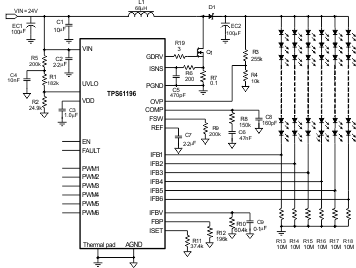
简化电路原理图

4 修订历史记录
| 日期 | 修订版本 | 注释 |
|---|---|---|
| 2015 年 3 月 | * | 最初发布。 |