ZHCSFG8A AUGUST 2013 – September 2016 TPS54418A
PRODUCTION DATA.
- 1 特性
- 2 应用范围
- 3 说明
- 4 简化电路原理图
- 5 Revision History
- 6 Pin Configuration and Functions
- 7 Specifications
-
8 Detailed Description
- 8.1 Overview
- 8.2 Functional Block Diagram
- 8.3
Feature Description
- 8.3.1 Fixed Frequency PWM Control
- 8.3.2 Slope Compensation and Output Current
- 8.3.3 Bootstrap Voltage (Boot) and Low Dropout Operation
- 8.3.4 Error Amplifier
- 8.3.5 Voltage Reference
- 8.3.6 Adjusting the Output Voltage
- 8.3.7 Enable and Adjusting Undervoltage Lockout
- 8.3.8 Soft-Start Pin
- 8.3.9 Sequencing
- 8.3.10 Constant Switching Frequency and Timing Resistor (RT/CLK Pin)
- 8.3.11 Overcurrent Protection
- 8.3.12 Frequency Shift
- 8.3.13 Reverse Overcurrent Protection
- 8.3.14 Synchronize Using the RT/CLK Pin
- 8.3.15 Power Good (PWRGD Pin)
- 8.3.16 Overvoltage Transient Protection
- 8.3.17 Thermal Shutdown
- 8.4 Device Functional Modes
-
9 Application and Implementation
- 9.1 Application Information
- 9.2
Typical Application
- 9.2.1 Design Requirements
- 9.2.2
Detailed Design Procedure
- 9.2.2.1 Step One: Select the Switching Frequency
- 9.2.2.2 Step Two: Select the Output Inductor
- 9.2.2.3 Step Three: Choose the Output Capacitor
- 9.2.2.4 Step Four: Select the Input Capacitor
- 9.2.2.5 Step Five: Minimum Load DC COMP Voltage
- 9.2.2.6 Step Six: Choose the Soft-Start Capacitor
- 9.2.2.7 Step Seven: Select the Bootstrap Capacitor
- 9.2.2.8 Step Eight: Undervoltage Lockout Threshold
- 9.2.2.9 Step Nine: Select Output Voltage and Feedback Resistors
- 9.2.2.10 Step 10: Select Loop Compensation Components
- 9.2.2.11 Power Dissipation Estimate
- 9.2.3 Application Curves
- 10Power Supply Recommendations
- 11Layout
- 12器件和文档支持
- 13机械、封装和可订购信息
1 特性
- 两个可在 4A 负载下获得高效率的 30mΩ(典型值)金属氧化物半导体场效应晶体管 (MOSFET)
- 开关频率:200kHz 至 2MHz
- 整个温度范围内的电压基准:0.8V ± 1%
- 同步至外部时钟
- 可调软启动/排序
- 欠压 (UV) 和过压 (OV) 电源正常输出
- 低运行和关断静态电流
- 安全启动至预偏置输出
- 逐周期电流限制、过热和频率折返保护
- 工作结温范围:-40°C 至 150°C
- 耐热增强型 3mm x 3mm 16 引脚超薄型四方扁平无引线 (WQFN) 封装
2 应用范围
- 低压、高密度电源系统
- 针对高性能数字信号处理器 (DSP),现场可编程栅极阵列 (FPGA),特定用途集成电路 (ASIC),和微处理器的负载点调节
- 宽带、网络互联及光纤通信基础设施
3 说明
TPS54418A 器件是一款功能全面的 6V、4A 同步降压电流模式转换器,该转换器集成有两个 MOSFET。
TPS54418A 器件通过集成 MOSFET、执行电流模式控制来减少外部组件数量、启用高达 2MHz 的开关频率来减小电感尺寸,并借助小型 3mm x 3mm 耐热增强型 QFN 封装尽量减小器件封装尺寸,从而实现小型设计。
TPS54418A 器件可在整个温度范围内为多种负载提供电压基准 (VREF) 精度达 ±1% 的准确调节。
通过集成型 30mΩ MOSFET 和典型值为 350μA 的电源电流可使效率得以大幅提升。通过使用使能引脚进入关断模式,关断电流可减少至 2µA。
欠压闭锁在内部设定为 2.6V,但可通过使能引脚上的电阻网络设定阈值将之提高。输出电压启动斜坡由软启动引脚控制。开漏电源状态良好信号表示输出处于其标称电压的 93% 至 107% 之内。频率折返和热关断功能在过流情况下保护器件不受损坏。
使用 SwitcherPro™电源设计软件来创建、管理和共享 TPS54418A 的定制电源设计,请单击此处。
要获得更多 SWIFT ™文档,请参见 TI 网站 www.ti.com/swift。
器件信息(1)
| 器件型号 | 封装 | 封装尺寸(标称值) |
|---|---|---|
| TPS54418A | WQFN (16) | 3.00mm x 3.00mm |
- 如需了解所有可用封装,请见数据表末尾的可订购产品附录。
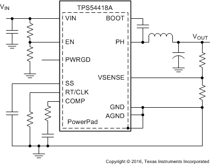
4 简化电路原理图

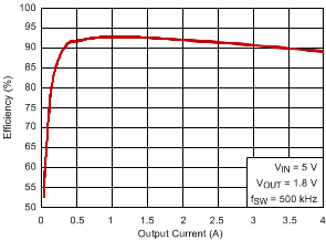
效率与输出电流间的关系
