ZHCS375E November   2011  – December 2015 TPS43340-Q1

PRODUCTION DATA.  

  1. 特性
  2. 应用
  3. 说明
  4. 修订历史记录
  5. Pin Configuration and Functions
  6. Specifications
    1. 6.1 Absolute Maximum Ratings
    2. 6.2 ESD Ratings
    3. 6.3 Recommended Operating Conditions
    4. 6.4 Thermal Information
    5. 6.5 Electrical Characteristics
    6. 6.6 Typical Characteristics
  7. Detailed Description
    1. 7.1 Overview
    2. 7.2 Functional Block Diagram
    3. 7.3 Feature Description
      1. 7.3.1 Enable Inputs
      2. 7.3.2 Linear Regulator (LREG1)
      3. 7.3.3 Gate-Driver Supply (VREG, EXTSUP)
      4. 7.3.4 External P-Channel Drive (GPULL) and Reverse Battery Protection
      5. 7.3.5 Undervoltage Lockout and Overvoltage Protection
      6. 7.3.6 Synchronous Buck Converter Buck3
        1. 7.3.6.1 Soft Start and Foldback Functions
        2. 7.3.6.2 Current-Mode Control and Current-Limit Protection
        3. 7.3.6.3 Operation in Dropout and Undervoltage Protection
        4. 7.3.6.4 Slew Rate Control (SLEW)
    4. 7.4 Device Functional Modes
      1. 7.4.1 Buck Controllers: Normal Mode PWM Operation
        1. 7.4.1.1 Setting the Operating Frequency
        2. 7.4.1.2 Feedback Inputs
        3. 7.4.1.3 Soft-Start Inputs
        4. 7.4.1.4 Current-Mode Operation
        5. 7.4.1.5 Current Sensing and Current Limit With Foldback
        6. 7.4.1.6 Slope Compensation
        7. 7.4.1.7 Reset Outputs and Filter Delays
        8. 7.4.1.8 Light-Load PFM Mode
  8. Application and Implementation
    1. 8.1 Application Information
    2. 8.2 Typical Application
      1. 8.2.1 Design Requirements
      2. 8.2.2 Detailed Design Procedure
        1. 8.2.2.1 High- and Low-Side Power NMOS Selection for the Buck Converters
        2. 8.2.2.2 Buck1 Component Selection
        3. 8.2.2.3 Buck2 Component Selection
        4. 8.2.2.4 Buck3 Component Selection
      3. 8.2.3 Application Curves
  9. Power Supply Recommendations
  10. 10Layout
    1. 10.1 Layout Guidelines
      1. 10.1.1 Grounding and PCB Circuit Layout Considerations
      2. 10.1.2 Other Considerations
    2. 10.2 Layout Example
    3. 10.3 Power Dissipation
      1. 10.3.1 Power Dissipation of Buck1 and Buck2 (VOUT1 and VOUT2)
      2. 10.3.2 Power Dissipation of Buck Converter Buck3 (VOUT3)
        1. 10.3.2.1 High-Side Switch
        2. 10.3.2.2 Low-Side Switch
        3. 10.3.2.3 Linear Regulator (LREG1)
        4. 10.3.2.4 IC Power Consumption
    4. 10.4 Thermal Considerations
      1. 10.4.1 Phase Configuration
  11. 11器件和文档支持
    1. 11.1 器件支持
      1. 11.1.1 Third-Party Products Disclaimer
    2. 11.2 文档支持
      1. 11.2.1 相关文档 
    3. 11.3 社区资源
    4. 11.4 商标
    5. 11.5 静电放电警告
    6. 11.6 Glossary
  12. 12机械、封装和可订购信息

封装选项

机械数据 (封装 | 引脚)
散热焊盘机械数据 (封装 | 引脚)
订购信息

特性

  • 适用于汽车电子 应用
  • 具有下列结果的 AEC-Q100 测试指南:
    • 器件温度 1 级:-40°C 至 125°C 的环境运行温度范围
    • 器件人体放电模式 (HBM) 静电放电 (ESD) 分类等级 H1
    • 器件组件充电模式 (CDM) ESD 分类等级 C3B
  • 输入电压范围最高达 40V(瞬态电压高达 60V)
  • 输入电压范围:4V 至 40V
    • 瞬态电压高达 60V
  • 双输入同步降压控制器
    • 峰值栅极驱动电流为 0.6A
    • 自动低功率模式运行
    • 低功耗模式 IQ:30µA(一个降压转换器工作),35µA(两个降压转换器工作)
  • 低关断电流,Ish = 5μA(典型值)
  • 单一同步降压调节器转换器 BUCK3
    • 最大输出电流 2A
  • 线性稳压器 LREG1
  • 独立的使能输入(EN1、EN2、EN3、EN4)
  • 内部振荡器,可借助外部电阻器进行编程,150kHz 至 600kHz 的开关频率fSW_BUCK1,2,3
  • 集成锁相环路 (PLL),外部同步频率:150kHz 至 600kHz
  • 以 180° 相移运行的开关模式稳压器
  • 用于所有输出电源轨的复位输出
  • 电源和过压检测及关断
  • 耐热增强型 PowerPAD™封装
    • 48 引脚带散热片方形扁平封装 (HTQFP) (PHP)

应用

  • 汽车信息娱乐系统、主机、导航、音频和仪表板
  • 高级驾驶员辅助系统 (ADAS)
  • 汽车和工业多轨直流配电系统

说明

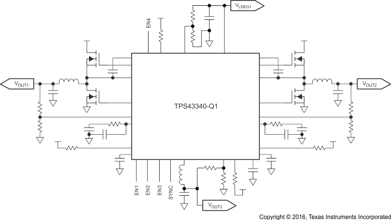
TPS43340-Q1 是一款四路轨电源,特有两个栅极驱动电流为 0.6A 的同步降压控制器、一个同步 2A 降压转换器以及一个具有低静态电流的 300mA LDO。该器件专为包括 MCU 和 DSP(分别直接通过汽车电池供电)在内的整个系统供电,输入电压最高为 40V。该器件 在 降压稳压器控制器的栅极驱动输出上集成了短路和过流保护功能,并且可在稳压器输出接地短路时单独为每个降压稳压器电源施加电流折返控制。每个输出电源包含一个软启动以确保最初加电时这些经稳压的输出不受电流限制的影响。加电时执行的复位延迟使得 Buck1,Buck2,Buck3 和线性稳压器的输出达到稳定调节。一个外部电容器将延迟设定为 300ms 的最大范围。每个电源输出具有可根据外部电阻器网络设置进行调节的输出电压。根据使能和禁用控制或者软启动,此器件可在输出电源轨加电和断电期间进行排序控制。

器件信息(1)

器件型号 封装 封装尺寸(标称值)
TPS43340-Q1 HTQFP (48) 7.00mm x 7.00mm
  1. 要了解所有可用封装,请见数据表末尾的可订购产品附录。

简化电路原理图

TPS43340-Q1 simplschem_lvsb16.gif