SLUS599B June 2004 – October 2015 TPS2400
PRODUCTION DATA.
- 1 Features
- 2 Applications
- 3 Description
- 4 Revision History
- 5 Pin Configuration and Functions
- 6 Specifications
- 7 Parameter Measurement Information
- 8 Detailed Description
- 9 Application and Implementation
- 10Power Supply Recommendations
- 11Layout
- 12Device and Documentation Support
- 13Mechanical, Packaging, and Orderable Information
8 Detailed Description
8.1 Overview
The TPS2400 device is used in applications that must protect the load from overvoltage event. Benefits include fast response time and survival during extended overvoltage events.
8.2 Functional Block Diagram

8.3 Feature Description
8.3.1 Undervoltage and Overvoltage Comparators and Logic
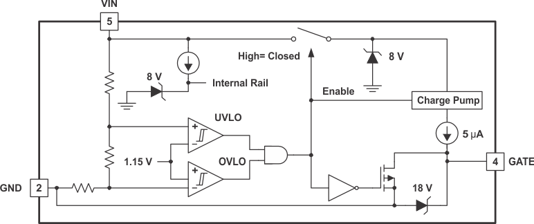
When the comparators detect that VCC is within the operating window, the GATE output is driven high to turn on the external N-channel MOSFET. When VCC goes above the set overvoltage level, or below the set undervoltage level, the GATE output is driven low.
8.3.2 Charge Pump
An internal charge pump supplies power to the GATE drive circuit and provides the necessary voltage to pull the gate of the MOSFET above the source.
8.3.3 Zener Diodes
Limit internal power rails to 8 V and GATE output to 18 V.
8.3.4 Shut-Off MOSFET
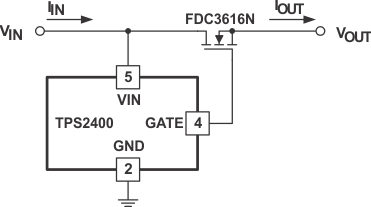
When an undervoltage or overvoltage event occurs, this MOSFET is turned on to pulldown the gate of the external N-channel MOSFET, thus isolating the load from the incoming transient.
 Figure 13. Application Diagram
8.4 Device Functional Modes
8.4.1 Overvoltage Protection
An overvoltage condition is commonly created in these situations:
- Unplugging a wall adapter from an AC outlet. Energy stored in the transformer magnetizing inductance is released and spikes the output voltage.
- Powering an appliance with the wrong voltage adapter (user error).
- Automotive load dump due to ignition, power windows, or starter motor (for example).
- An AC power-line transient.
- Power switch contact bounce (causes power supply/distribution inductive kick), (See Figure 14).
Many electronic appliances use a transient voltage suppressor (TVS) for overvoltage protection as shown in Figure 14. The TVS is typically a metal-oxide varister (MOV) or Transzorb. The former is a nonlinear resistor with a soft turnon characteristic whereas the latter is a large junction Zener diode with a very sharp turnon characteristic. These devices have high pulse-power capability and pico-second response time. A TVS clamps the load voltage to a safe level so the load operates uninterrupted in the presence of power supply output-voltage spikes. But in the event of a voltage surge, fuse F2 blows and must be replaced to restore operation.
 Figure 14. Load Protection Using Transient Voltage Suppressor Clamps
The TPS2400 circuit in Figure 15 protects the load from an overvoltage, not by clamping the load voltage like a TVS, but by disconnecting the load from the power supply. The circuit responds to an overvoltage in less than 1 µs and rides out a voltage surge without blowing fuse F2. The voltage surge can be of indefinite duration.
The load can see a voltage spike of up to 1 µs, the amount of time it takes the TPS2400 to disconnect the load from the power supply. A low-power Zener diode D2 can be used to clamp the load voltage to a safe level. In most cases, diode D2 is not necessary because the load bypass capacitor (not shown) forms a low-pass filter with resistor RS and inductor LS to significantly attenuate the spike.