ZHCS233D May   2011  – May 2017 SN65HVD101 , SN65HVD102

PRODUCTION DATA.  

  1. 特性
  2. 应用
  3. 说明
  4. 修订历史记录
  5. Device Comparison Table
  6. Pin Configuration and Functions
  7. Specifications
    1. 7.1 Absolute Maximum Ratings
    2. 7.2 ESD Ratings
    3. 7.3 Recommended Operating Conditions
    4. 7.4 Thermal Information
    5. 7.5 Electrical Characteristics
    6. 7.6 Switching Characteristics
    7. 7.7 Typical Characteristics
  8. Parameter Measurement
  9. Detailed Description
    1. 9.1 Overview
    2. 9.2 Functional Block Diagram
    3. 9.3 Feature Description
      1. 9.3.1 Wake-up Detection
      2. 9.3.2 Current Limit Indication - Short Circuit Current Detection
      3. 9.3.3 Active Current Limit Condition: VTHL > VCQ ≥ VTHH
      4. 9.3.4 Inactive Current Limit Condition: VTHL < VCQ < VTHH
      5. 9.3.5 Over-temperature Detection
      6. 9.3.6 CQ Current-limit Adjustment
      7. 9.3.7 Transceiver Function Tables
      8. 9.3.8 Voltage Regulator (Not Available in SN65HVD102)
    4. 9.4 Device Functional Modes
  10. 10Application and Implementation
    1. 10.1 Application Information
    2. 10.2 Typical Application
      1. 10.2.1 Design Requirements
      2. 10.2.2 Detailed Design Procedure
        1. 10.2.2.1 Transceiver Configuration (SN65HVD101)
        2. 10.2.2.2 Maximum Ambient Temperature Check
        3. 10.2.2.3 Transient Protection
        4. 10.2.2.4 TVS Evaluation
      3. 10.2.3 Application Curves
    3. 10.3 System Examples
      1. 10.3.1 Driver for Incandescent Lamp Loads
      2. 10.3.2 Driver for Inductive Loads
  11. 11Power Supply Recommendations
  12. 12Layout
    1. 12.1 Layout Guidelines
    2. 12.2 Layout Example
  13. 13器件和文档支持
    1. 13.1 相关链接
    2. 13.2 接收文档更新通知
    3. 13.3 社区资源
    4. 13.4 商标
    5. 13.5 静电放电警告
    6. 13.6 Glossary
  14. 14机械、封装和可订购信息

封装选项

机械数据 (封装 | 引脚)
散热焊盘机械数据 (封装 | 引脚)
订购信息

Parameter Measurement

SN65HVD101 SN65HVD102 drv_out_llse84.gif
Figure 3. Waveforms for Driver Output Switching Measurements
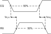
SN65HVD101 SN65HVD102 RX_swt_llse84.gif
Figure 5. Receiver Switching Measurements
SN65HVD101 SN65HVD102 drv_enable_llse84.gif
Figure 4. Waveform for Driver Enable/Disable Time Measurements
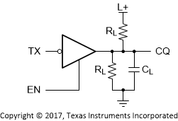
SN65HVD101 SN65HVD102 test_cir_llse84.gif
Figure 6. Test Circuit for Driver Switching