SBOS058A December 1997 – October 2015 OPA134 , OPA2134 , OPA4134
PRODUCTION DATA.
- 1 Features
- 2 Applications
- 3 Description
- 4 Revision History
- 5 Pin Configuration and Functions
- 6 Specifications
- 7 Detailed Description
- 8 Application and Implementation
- 9 Power Supply Recommendations
- 10Layout
- 11Device and Documentation Support
- 12Mechanical, Packaging, and Orderable Information
封装选项
机械数据 (封装 | 引脚)
散热焊盘机械数据 (封装 | 引脚)
- D|8
订购信息
7 Detailed Description
7.1 Overview
The OPA134 series are ultra-low distortion, low-noise operational amplifiers fully specified for audio applications. A true FET input stage is incorporated to provide superior sound quality and speed for exceptional audio performance. This, in combination with high output drive capability and excellent DC performance, allows for use in a wide variety of demanding applications. In addition, the OPA134 has a wide output swing, to within 1 V of the rails, allowing increased headroom and making it ideal for use in any audio circuit.
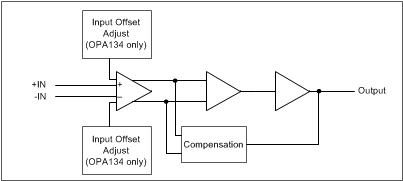
7.2 Functional Block Diagram

7.3 Feature Description
7.3.1 Total Harmonic Distortion
The OPA134 series of operational amplifiers have excellent distortion characteristics. THD+Noise is below 0.0004% throughout the audio frequency range, 20 Hz to 20 kHz, with a 2-kΩ load. In addition, distortion remains relatively flat through its wide output voltage swing range, providing increased headroom compared to other audio amplifiers, including the OP176/275.
Headroom is a subjective measurement, and can be thought of as the maximum output amplitude allowed while still maintaining a low level of distortion. In an attempt to quantify headroom, TI defines very low distortion as 0.01%. Headroom is expressed as a ratio which compares the maximum allowable output voltage level to a standard output level (1 mW into 600 Ω, or 0.7746 Vrms). Therefore, OPA134 series of operational amplifiers, which have a maximum allowable output voltage level of 11.7 Vrms (THD+Noise < 0.01%), have a headroom specification of 23.6 dBu. See Figure 4.
7.3.2 Distortion Measurements
The distortion produced by OPA134 series of operational amplifiers is below the measurement limit of all known commercially-available equipment. However, a special test circuit can extend the measurement capabilities.
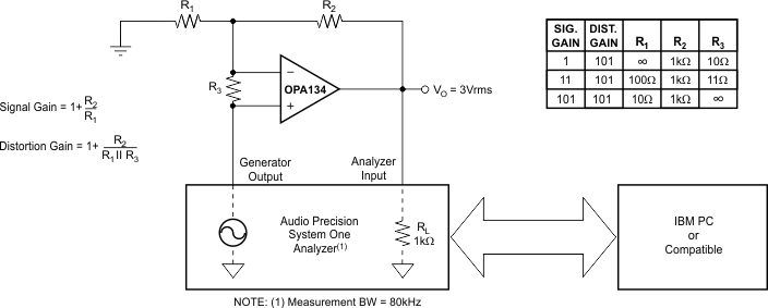
Operational amplifier distortion can be considered an internal error source which can be referred to the input. Figure 27 shows a circuit which causes the operational amplifier distortion to be 101 times greater than that which the operational amplifier normally produces. The addition of R3 to the otherwise standard non-inverting amplifier configuration alters the feedback factor or noise gain of the circuit. The closed-loop gain is unchanged, but the feedback available for error correction is reduced by a factor of 101, thus extending the resolution by 101. The input signal and load applied to the operational amplifier are the same as with conventional feedback without R3. The value of R3 should be kept small to minimize its effect on the distortion measurements.
 Figure 27. Distortion Test Circuit
This technique can be verified by duplicating measurements at high gain or high frequency, where the distortion is within the measurement capability of the test equipment. Measurements for this data sheet were made with an Audio Precision distortion and noise analyzer, which greatly simplifies repetitive measurements. The measurement technique can, however, be performed with manual distortion measurement instruments.
7.3.3 Source Impedance and Distortion
For lowest distortion with a source or feedback network with an impedance greater than 2 kΩ, the impedance seen by the positive and negative inputs in noninverting applications should be matched. The p-channel JFETs in the FET input stage exhibit a varying input capacitance with applied common-mode input voltage. In inverting configurations, the input does not vary with input voltage, because the inverting input is held at virtual ground. However, in noninverting applications the inputs do vary, and the gate-to-source voltage is not constant. The effect is increased distortion due to the varying capacitance for unmatched source impedances greater than 2 kΩ.
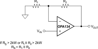
To maintain low distortion, match unbalanced source impedance with the appropriate values in the feedback network as shown in Figure 28. Of course, the unbalanced impedance may be from gain-setting resistors in the feedback path. If the parallel combination of R1 and R2 is greater than 2 kΩ, use a matching impedance on the noninverting input. As always, minimize resistor values to reduce the effects of thermal noise.
 Figure 28. Impedance Matching for Maintaining Low Distortion in Non-Inverting Circuits
7.3.4 Phase Reversal Protection
The OPA134 series of operational amplifiers are free from output phase-reversal problems. Many audio operational amplifiers, such as the OP176, exhibit phase-reversal of the output when the input common-mode voltage range is exceeded. This can occur in voltage-follower circuits, causing serious problems in control loop applications. The OPA134 series operational amplifiers are free from this undesirable behavior even with inputs of 10-V beyond the input common-mode range.
7.3.5 Output Current Limit
Output current is limited by internal circuitry to approximately ±40 mA at 25°C. The limit current decreases with increasing temperature, as shown in Figure 19.
7.4 Device Functional Modes
7.4.1 Noise Performance
Circuit noise is determined by the thermal noise of external resistors and operational amplifier noise. Operational amplifier noise is described by two parameters: noise voltage and noise current. The total noise is quantified by the equation:

With low source impedance, the current noise term is insignificant and voltage noise dominates the noise performance. At high source impedance, the current noise term becomes the dominant contributor.
Low-noise bipolar operational amplifiers such as the OPA27 and OPA37 provide low voltage noise at the expense of a higher current noise. However, OPA134 series operational amplifiers provide both low voltage noise and low current noise. This provides optimum noise performance over a wide range of sources, including reactive source impedances; refer to Figure 6. Above 2-kΩ source resistance, the operational amplifier contributes little additional noise; the voltage and current terms in the total noise equation become insignificant and the source resistance term dominates. Below 2 kΩ, operational amplifier voltage noise dominates over the resistor noise, but compares favorably with other audio operational amplifiers such as the OP176.