SNVS052E September 1999 – April 2016 LM809 , LM810
PRODUCTION DATA.
- 1 Features
- 2 Applications
- 3 Description
- 4 Revision History
- 5 Pin Configuration and Functions
- 6 Specifications
- 7 Detailed Description
- 8 Application and Implementation
- 9 Power Supply Recommendations
- 10Layout
- 11Device and Documentation Support
- 12Mechanical, Packaging, and Orderable Information
8 Application and Implementation
NOTE
Information in the following applications sections is not part of the TI component specification, and TI does not warrant its accuracy or completeness. TI’s customers are responsible for determining suitability of components for their purposes. Customers should validate and test their design implementation to confirm system functionality.
8.1 Application Information
The LM809 and LM810 are a supervisor circuit for microprocessor and digital systems. With a low supply current of only 15 µA, the LM809 and LM810 are ideal for use in portable equipment.
8.2 Typical Application
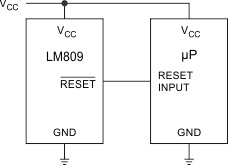
 Figure 10. Microprocessor RESET Circuit
8.2.1 Design Requirements
For this design example, use the parameters listed in Table 2 as the input parameters.
Table 2. Design Parameters
| DESIGN PARAMETER | EXAMPLE VALUE |
|---|---|
| Input supply voltage range | 1 V to 5.5 V |
| Reset output voltage (high) | Input supply |
| Reset output voltage (low) | 0 V |
8.2.2 Detailed Design Procedure
For the typical application circuit, all that is required is the LM809 or LM810 IC, but TI recommends an input capacitor to help with input voltage transients. A typical input capacitor value is 0.1 uF and must be rated for the highest expected input voltage.
8.2.3 Application Curve
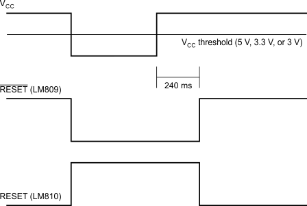
 Figure 11. Reset Active Timeout