ZHCSIU0D February 2000 – September 2018 LM4051-N
PRODUCTION DATA.
- 1 特性
- 2 应用
- 3 说明
- 4 修订历史记录
- 5 Pin Configuration and Functions
- 6 Specifications
- 7 Parameter Measurement Information
- 8 Detailed Description
- 9 Application and Implementation
- 10Power Supply Recommendations
- 11Layout
- 12器件和文档支持
- 13机械、封装和可订购信息
请参考 PDF 数据表获取器件具体的封装图。
机械数据 (封装 | 引脚)
- DBZ|3
散热焊盘机械数据 (封装 | 引脚)
9.3 System Examples
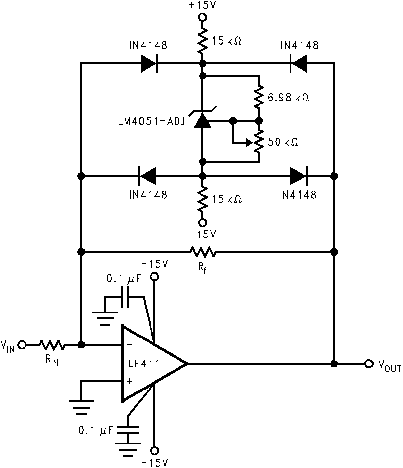 Figure 21. Bounded Amplifier Reduces Saturation-induced Delays and Can Prevent Succeeding Stage Damage. Nominal Clamping Voltage is ±VO (LM4051-N's Reverse Breakdown Voltage) +2 Diode VF .
 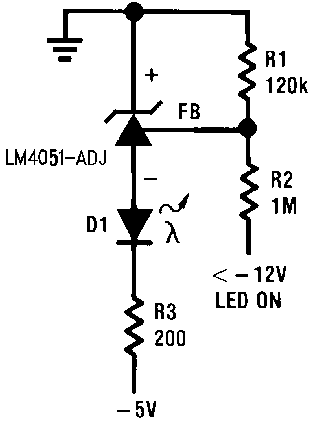 Figure 22. Voltage Level Detector
 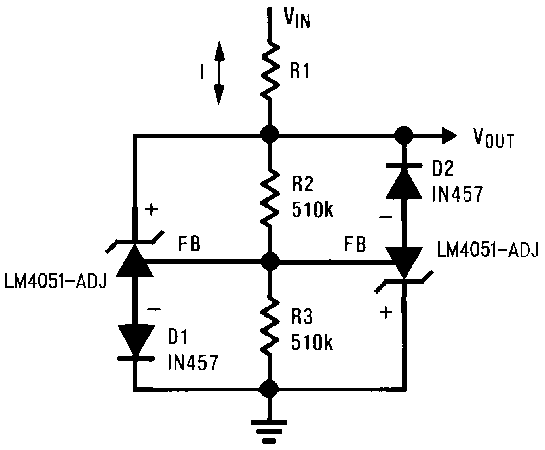 Figure 23. Voltage Level Detector
 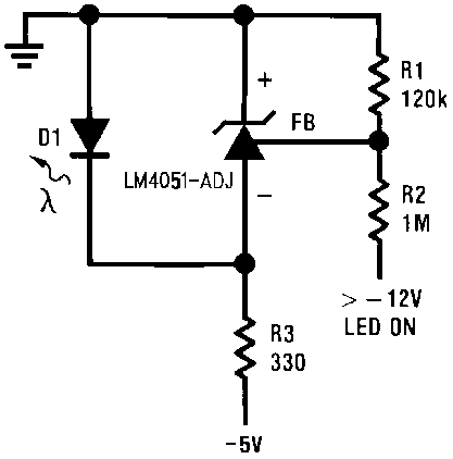 Figure 24. Fast Positive Clamp 2.4V + VD1
 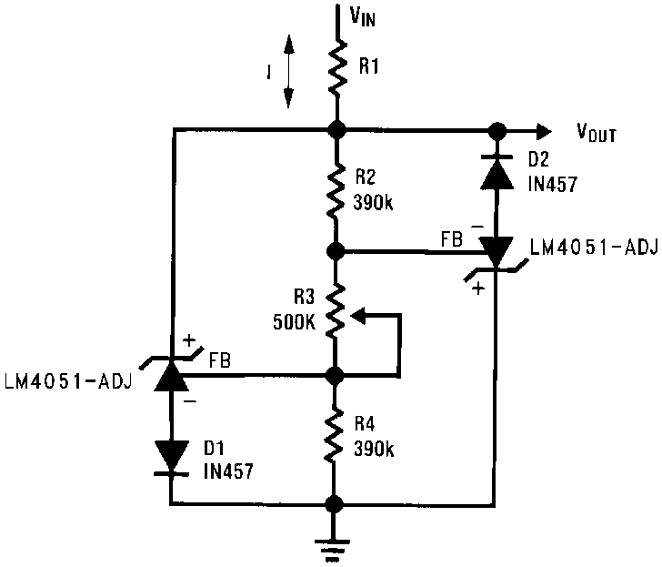 Figure 25. Bidirectional Clamp ± 2.4V
 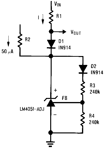 Figure 26. Bidirectional Adjustable Clamp ± 18V to ± 2.4V
 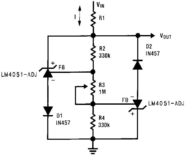 Figure 27. Bidirectional Adjustable Clamp ± 2.4V to ± 6V
 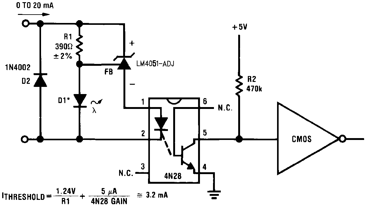 Figure 28. Simple Floating Current Detector
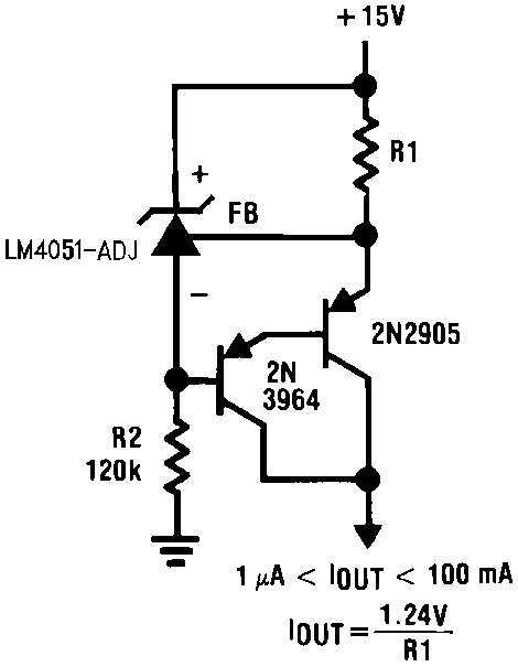
*D1 can be any LED, VF = 1.5V to 2.2V at 3 mA. D1 may act as an indicator. D1 will be on if ITHRESHOLD falls below the threshold current, except with I = O.
Figure 29. Current Source 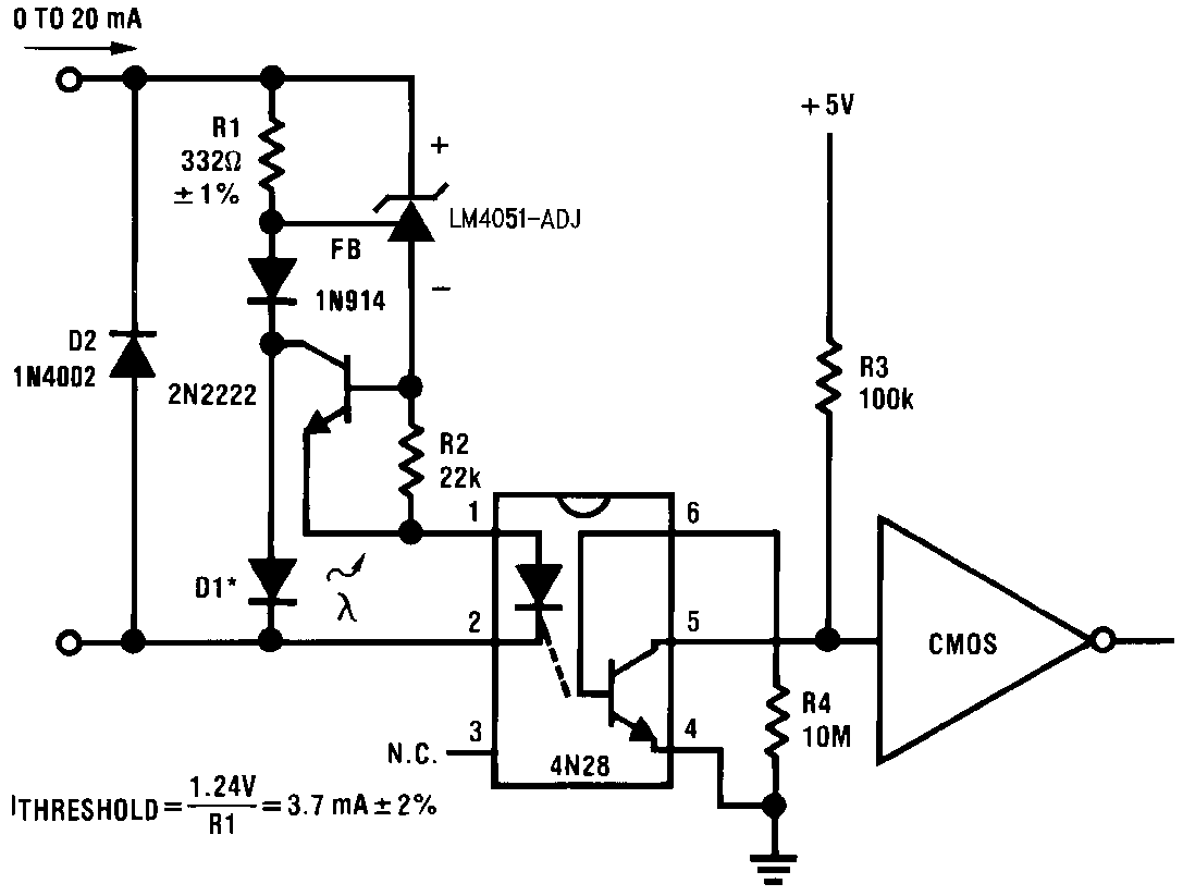 Figure 30. Precision Floating Current Detector
 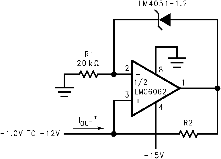 Figure 31. Precision 1 μA to 1 mA Current Source
 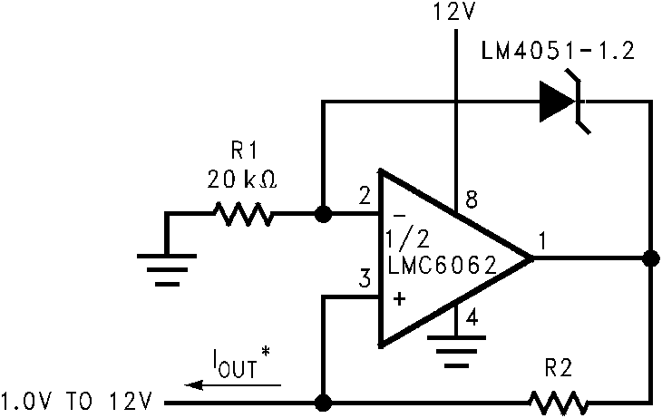 Figure 32. Precision 1 μA to 1 mA Current Source