SNIS115S May 2001 – September 2015 LM26
PRODUCTION DATA.
- 1 Features
- 2 Applications
- 3 Description
- 4 Revision History
- 5 Device Comparison Table
- 6 Pin Configuration and Functions
- 7 Specifications
- 8 Detailed Description
- 9 Application and Implementation
- 10Power Supply Recommendations
- 11Layout
- 12Device and Documentation Support
- 13Mechanical, Packaging, and Orderable Information
9 Application and Implementation
NOTE
Information in the following applications sections is not part of the TI component specification, and TI does not warrant its accuracy or completeness. TI’s customers are responsible for determining suitability of components for their purposes. Customers should validate and test their design implementation to confirm system functionality.
9.1 Application Information
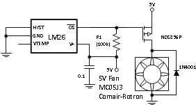
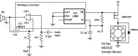
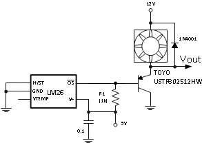
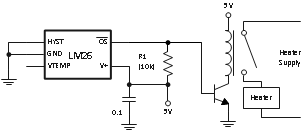
The LM26 thermostat (temperature switch) can be used in applications such as microprocessor thermal management, appliances, fan control, industrial process control, power supplies for system protection, fan speed adjust or plain temperature monitoring.
9.2 Typical Application
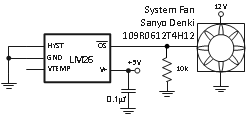 Figure 8. Two-Speed Fan Speed Control
9.2.1 Design Requirements
The requirement is to change speed fo a fan to maximum at 45°C with an accuracy of
Table 2. Design Parameters
| DESIGN PARAMETER | EXAMPLE VALUE | |||
|---|---|---|---|---|
| Min Fan Speed | 1900 RPM | |||
| Max Fan Speed | 3800 RPM | |||
| Temperature Threshold To Switch From Min Speed to Max Speed | 45°C | |||
| Threshold accuracy | ±3°C | |||
9.2.2 Detailed Design Procedure
The design procedure is simple. A fan was selected that has the capability to be controlled by an external NTC thermistor. The recommended NTC thermistor adjusts the fan speed to maximum at 40°C. The LM26 meets the threshold accuracy requirements for temperature control of the fan speed and allows setting the max speed temperature threshold higher as required to 45°C. The resistance of the thermistor for the min fan speed is 6.8 kΩ. Since thermistors have a negative temperature coefficient (NTC), 10 kΩ was chosen to ensure that the fan is at min speed when the LM26 OS is off. When the OS output goes low at 45°C it simulates the low thermistor resistance at higher temperatures thus setting fan to max speed.
9.2.3 Application Curve
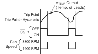 Figure 9. Temperature Effect on Fan Speed
